Page Content
| Table of Contents | ||||||||||||||||||
|---|---|---|---|---|---|---|---|---|---|---|---|---|---|---|---|---|---|---|
|
Have a question or need help?
| Auibutton | ||||||||||||||||||||||||||||||
|---|---|---|---|---|---|---|---|---|---|---|---|---|---|---|---|---|---|---|---|---|---|---|---|---|---|---|---|---|---|---|
|
Solution
| Cfm tabs page | ||||||||||||
|---|---|---|---|---|---|---|---|---|---|---|---|---|
| ||||||||||||
OPAL-RT provides ARINC AFDX solution for Hardware-in-the-Loop (HIL) and rapid control prototyping (RCP) applications, such as full authority digital engine/electronic control (FADEC) and aircraft system components testing. |
| Cfm tabs page | ||||||||||
|---|---|---|---|---|---|---|---|---|---|---|
| ||||||||||
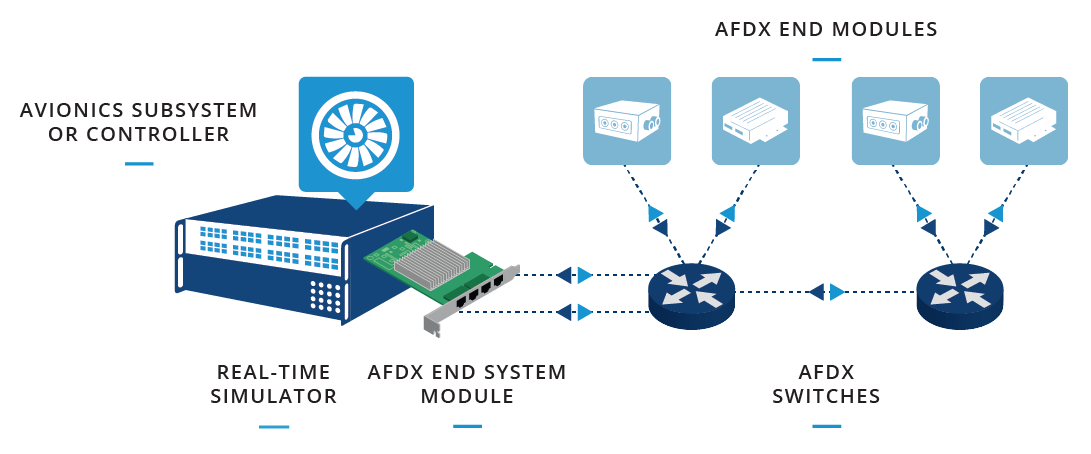
AFDX (Avionics Full Duplex Switched Ethernet) is a communications network defined in the ARINC-664, Part 7 standard for the exchange of data between avionics subsystems. AFDX is based on ethernet technology and adapted to the avionics environment. The major components of avionics networks are the avionics subsystem (e.g., flight control system, GPS, TPMS, etc.) and the AFDX end system, which acts as an interface between various avionics subsystems via switched ethernet network. The major concepts of this protocol are full duplex, redundancy, determinism, high-speed performance, switched and profile network. The AFDX PCIe card will behave as a switch between end devices, capable of receiving and transmitting. |
Software Platform Compatibility
| Auibutton | ||||||||||||||||||||||||||
|---|---|---|---|---|---|---|---|---|---|---|---|---|---|---|---|---|---|---|---|---|---|---|---|---|---|---|
|
Product Selection Guide
To add AFDX/ARINC 664 P7 capabilities to a simulator, one of the following options can be added, depending on the type of connection required (standard Ethernet cable (copper) or fiber-optic) and the compatible simulator model.
| Info |
|---|
Simulator must have available PCIe slot. |
Ethernet Cable (Copper)
Type | Description | Product Number | Simulator Compatibility | ||
OP5033XG | OP5600v2 | OP5700 | |||
Hardware | AFDX bus interface kit*. The kit includes:
| OP3530-5030-CO | YES | ||
OP3530-5600-CO | YES | ||||
OP3530-5700-CO | YES | ||||
* Available PCIe slot required
Fiber-Optic Cable
Type | Description | Product Number | Simulator Compatibility | ||
OP5033XG | OP5600V2 | OP5700 | |||
Hardware | AFDX bus interface kit*. The kit includes:
| OP3530-5030-FO | YES | ||
OP3530-5600-FO | YES | ||||
OP3530-5700-FO | YES | ||||
* Available PCIe slot required