| Table of Contents |
|---|
...
| |
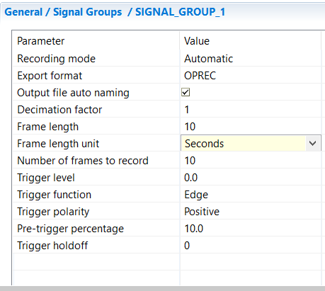
PARAMETER | VALUE |
|---|---|
| Recording mode |
This depends on the configured parameter. Recording may stop before the reset of the model. |
Export format | OPREC (native format), Comma-Separated Values (CSV EXCEL), or MATLAB |
Output file auto naming | [selector] When selected, new parameter Output file name [String] is available to provide a specific file name. Check this checkbox to avoid naming collisions as it ensures naming uniqueness by appending the timestamp to the filename. It also, if checked, names the output files based on a combination of the model name, the subsystem name, the date and hour for ease of management. Note that the seconds in the generated file name corresponding to the time at which the DataLogger prepares the recorded/saved file. This may occur just before the recording starts, or at some time before when a trigger is configured. When unchecked, no timestamp is appended to the name. So multiple simulation runs will overwrite the output file if it has not been renamed/moved between each simulation start |
Decimation factor | [long value] Specifies the logging frequency based on a factor of the simulation time step. For instance, if decimation factor = 1 the data is saved every step. If decimation factor = 2, the data is saved every 2 steps. And so on. |
| Frame length | [long value] A frame corresponds to the number of consecutive steps without any loss. Depending on the hardware configuration, some steps may be lost between two frames. This zone of possibly lost data is called the blind area. This area is not visible and is thus not captured by the data logging system. Because the data are stored to a file, users may see missing samples between these frames. The size of the blind area depends on many factors such as the number of signals stored, the sampling frequency, the speed of the simulator, the disk speed, etc. The 'Frame length' parameter specifies how many steps are to be recorded without any data loss (default 1000 steps). Default value is 1 second (default frame length unit). |
| Frame length unit | Defines the unit of the Frame length parameter. Default unit is in Seconds.
|
| Number of frames to record | [long value] Specifies how many frames to record. Note that there is no data loss within a frame but it may happen between frames. |
Trigger level | [double value] Level value that activates trigger. If a value of, say, 80 is set then recording starts when the trigger-signal rises past 80. |
Trigger function | Signal function that will cause a trigger event (Edge, Level) NOTE:
|
Trigger polarity | Triggers when the trigger signal is greater (Positive) or less (Negative) than the parameter Trigger Level. Together with the Trigger function and level, this parameter determines the trigger condition: When the Trigger function is set to EDGE:
When the Trigger function is set to LEVEL:
|
Pre-trigger percentage | Percentage of frame length allocated to values before trigger i.e. no start of recording till this percentage of the frame length, after the trigger event has passed. |
Trigger holdoff | [long value] Number of steps to ignore after a record is completed before re-arming trigger detection |

...
- Recording of Real-Time simulation data is limited to 2GB for real-time simulation on real-time targets (32bit). When using localhost targets, there is no known limitation to the logging file size.
- Occasional freezes in RT-LAB software may be experienced, especially with a high number of signals/signals_groups to log.
- When logging using vectors, all the elements of the vector are logged and there is no possibility to select only a subsection of the vector for recording.
- The export format to .mat file is very limited for now. A workaround is to use the .csv export format or to exploit .oprec files with MATLAB functions (cf. next section).
| Anchor | ||||
|---|---|---|---|---|
|
Exploiting OPREC files with MATLAB
Two MATLAB functions : OpRecInfo and OpRecRead are available to retrieve information and/or read data from OPAL Record files (.oprec).
...