| Table of Contents | ||||
|---|---|---|---|---|
|
Location
This example model can be found in the software under Renewable Energy > Type4_WindFarm_33kV.ecf
Description
Background
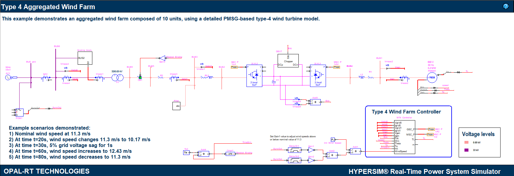
Type 4 wind turbine is one of the popular architectures of grid connected wind energy system. This example model demonstrates the implementation of a Type 4 Wind farm.
Model description
Electrical model
The example shows the simulation of an aggregated wind farm (WF), using a detailed electromagnetic model of a PMSG-based Type-4 wind turbine (WT). The electrical part of the model is inspired from [1] and the wind turbine characteristics used are that of GE wind turbine [2]. Each unit of the WT is rated at 5MW, and the user has the option to enter the number of WT units in a WF. The scaling block scales by the number of turbine units the output power coming from the collector system. The aggregated WT is connected to a simplified 33kV, 50Hz collector system emulating a grid. The nominal wind speed for the WTs is 11.3m/s.
Operation mechanism
The WT model principle schematic is illustrated in figure below. The turbine shaft is coupled to a permanent magnet synchronous generator (PMSG), and its stator windings are connected to a back-to–back converter based on two-level voltage source converters. The Machine Side Converter (MSC) controls the power drawn from the generator and the generator terminal voltage. The reference for the terminal voltage is 1pu and implements the flux weakening control so that the MSC provides the right amount of reactive current (flux weakening current) to have sufficient electromagnetic torque to meet the load torque and keeping the speed constant [3]. The power reference for the MSC is provided by the wind turbine model block.
The Grid Side Converter (GSC) is operated to control the DC link voltage and the reactive power. The voltage loop maintains the DC link voltage at 1450 V, while the reactive power control loop is set to unity power factor. A DC chopper with a dump load is also connected to the DC link to protect the converters from over voltages. The chopper operates when the DC link voltage exceeds 1667.5 V (1.15 pu) and is turned off when the voltage goes below 1522.5 V (1.05 pu).
For more detail about Permanent Magnet Synchronous Machine (PMSM)


Mechanical model
The wind turbine mechanical model [2] combines the empirical characteristics with blade pitch control to regulate the generator speed at the rated value (900 rpm). If the available power (or measured output power) is less than 27%, the turbine is brought to a lower speed, all with the philosophy of extracting the maximum available power. The control references are calculated by the wind turbine to torque converter block. The block implements the following functions and is inspired from the model in [1]
PMSG speed reference calculation:
The speed power relationship of the generator is modeled as
| Mathblock | ||
|---|---|---|
| ||
W_{ref}=-0.75P^2+1.59P+0.63 -----(1) |
The nominal reference speed for the generator is 1pu and is reduced below power levels of 0.27pu. Where, 𝑃 is the power extracted from the generator (sum of the power measured on the collector side of the turbine transformer and the power dissipated in the chopper) and 𝜔𝑟𝑒𝑓 is the reference speed for the PMSM
Speed control loop:
The speed control loop is used to produce the reference power for the MSC to extract from the generator to maintain the rotor speed at the reference speed calculated by (1)

Tip speed ratio calculation:
The tip speed ratio 𝜆 is calculated using the formula
| Mathblock | ||
|---|---|---|
| ||
\lambda=\frac{{w_r}R}{v_w} -----(2) |
Where, 𝜔𝑟 is the rotor speed in rad/s, 𝑅 is the turbine radius in meters and 𝑣𝑤 is the wind speed in 𝑚/𝑠.
Power regulation by pitch control loop:
The power control loop regulates the power sent to the grid at the rated value by altering the pitch as shown in figure below. The model is designed to always maximize the power extracted from the wind as long as it is within the system rating. If the power available in the wind is more than the system rating, the pitch angle will be increased to reduce the power extracted from the wind to the rated value, disabling the maximum power point tracking.

Load torque calculation using the wind power model:
The power available in the wind is modeled by the following equation:
| Mathblock | ||
|---|---|---|
| ||
P_{wind}={\frac{\rho}{2}}{A_r}{v_w}^3{C_p}(\lambda,\beta) ------(3) |
Where,
𝑃𝑤𝑖𝑛𝑑is the power extracted from the wind
ρ is the air density in 𝑘𝑔/𝑚3
𝐴𝑟is the area swept by the turbine blades in 𝑚2
𝑣𝑤is the wind speed in m/s
𝐶𝑝is the power coefficient and is a function of the tip speed ratio and
𝜆 as defined in (2) and the blade pitch angle, 𝛽.
The 𝐶𝑝 function ultimately gives a measure of the efficiency of the turbine (by design) to harvest power as a function of the tip speed ratio. It is given as a family of curves which differ at different blade pitch angles. The 𝐶𝑝 function is modeled as a fourth order, two variable polynomial as defined by the equation (4).
| Mathblock | ||
|---|---|---|
| ||
C_p(\lambda,\beta)=\sum_{m=0}^{4}{\sum_{n=0}^{4}}{\alpha_{mn}}{\beta^m}{\lambda^n} ------(4) |
The Cp function used in the model is characterized by the coefficients presented in table below
Model parameters
System parameters
| S. No | Name | Unit | Value |
|---|---|---|---|
| 1 | GSC Capacitor - CGSC | mF | 0.7 |
| 2 | GSC Filter - FGSC [R L C] | [Ω uH uF] | [1.332 621 0.35350] |
| 3 | GSC Choke - LGSC | uH | 150135 |
| 4 | DC Link Capacitor - Cdc | mF | 40 |
| 5 | Chopper Resistance - Rchop | Ω | 0.4636 |
| 6 | MSC Choke - LMSC | uH | 105 |
| 7 | MSC Capacitor - CMSC | uF | 0.7 |
80 | |||
Transformer parameters | |||
| 87 | Rated Voltage - Vpri /Vsec (Star-Delta lagging) | V | 33k/690 |
| 98 | Rated Power - Srated | MVA | 5.65 |
| 109 | Rated Frequency - frated | Hz | 50 |
| 1110 | Primary resistance - Rp | Ω | 0.4158 |
| 1211 | Primary inductance - Lp | H | 0.0630250378 |
| 1312 | Secondary resistance - Rs | uΩ | 5418.535186 |
| 1413 | Secondary inductance - Ls | uH | 8216.66254 |
| 1514 | Magnetizing Resistance - Rm | Ω | 73333 |
| 1615 | Magnetizing Inductance - Lm | H | 157.56 |
Wind Turbine parameters
| S. No | Name | Unit | Value | ||||
|---|---|---|---|---|---|---|---|
| 1 | Turbine radius - Rturb | m | 63 | ||||
| 2 | Turbine Rated Speed - nturb rated | rpm | 12.1 | ||||
| 3 | Pitch Angle - | degree | [0 27] |
PMSG parameters
| S. No | Name | Unit | Value | ||||
|---|---|---|---|---|---|---|---|
| 1 | Rated Voltage - Vrated | V | 690 | ||||
| 2 | Rated Power -Prated | MW | 5.2 | ||||
| 3 | No. of Poles - p | -- | 4 | ||||
| 4 | Rated Speed - nrpm | rpm | 900 | ||||
| 5 | Electrical Frequency - ferated | Hz | 30 | ||||
| 6 | Stator Resistance - Rs | Ωpu | 0.0173 | ||||
| 7 | Stator Inductances - Ls | Hpu | [0.543 1.086] | ||||
| 8 | Inertia constant (including the Turbine) - H | s | 3.5 | 9 | Flux magnet - Φ | Wb2.9888 |
Simulation and results
The below table shows the various test scenarios performed on Type 4 Wind farm model. The results are shown in the figure below. The model was tested at a time-step of 50 µs. The number of wind turbines considered are 10 (that is 50MW nominal power of the wind farm).
| Operating points | From | To | Wind speed (m/s) | Scenario |
|---|---|---|---|---|
| 1 | 0 s | 20 s | 11.3 m/s | Maintain nominal wind speed |
| 2 | 20 s | 30 s | 10.17 m/s | Wind speed decrease by 10% |
| 3 | 30 s | 31 s | 10.17 m/s | Voltage sag of 5% |
| 4 | 60 s | 80 s | 12.43 m/s | Wind speed increase by 20% |
| 5 | 80 s | 100 s | 11.3 m/s | restored to nominal wind speed |
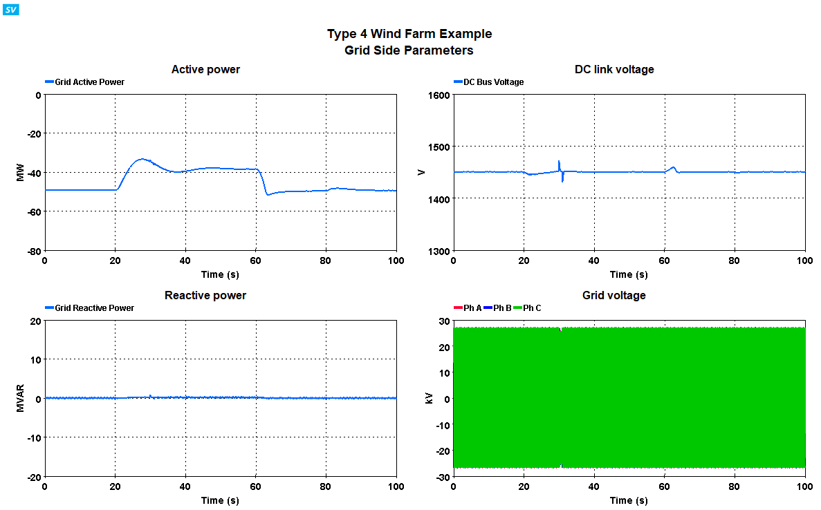
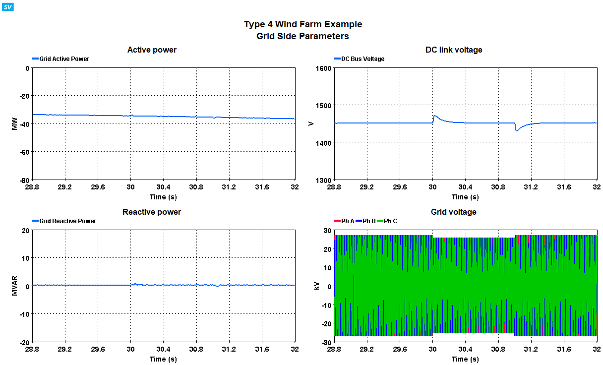
Figures below show the complete simulation window with all the scenarios for a 50MW wind farm. Please note that -ve negative values of grid power shows the power into the grid as per convention.


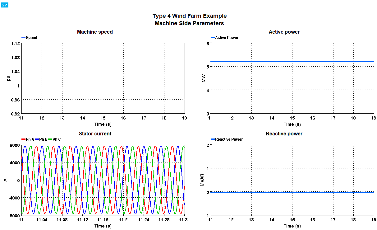
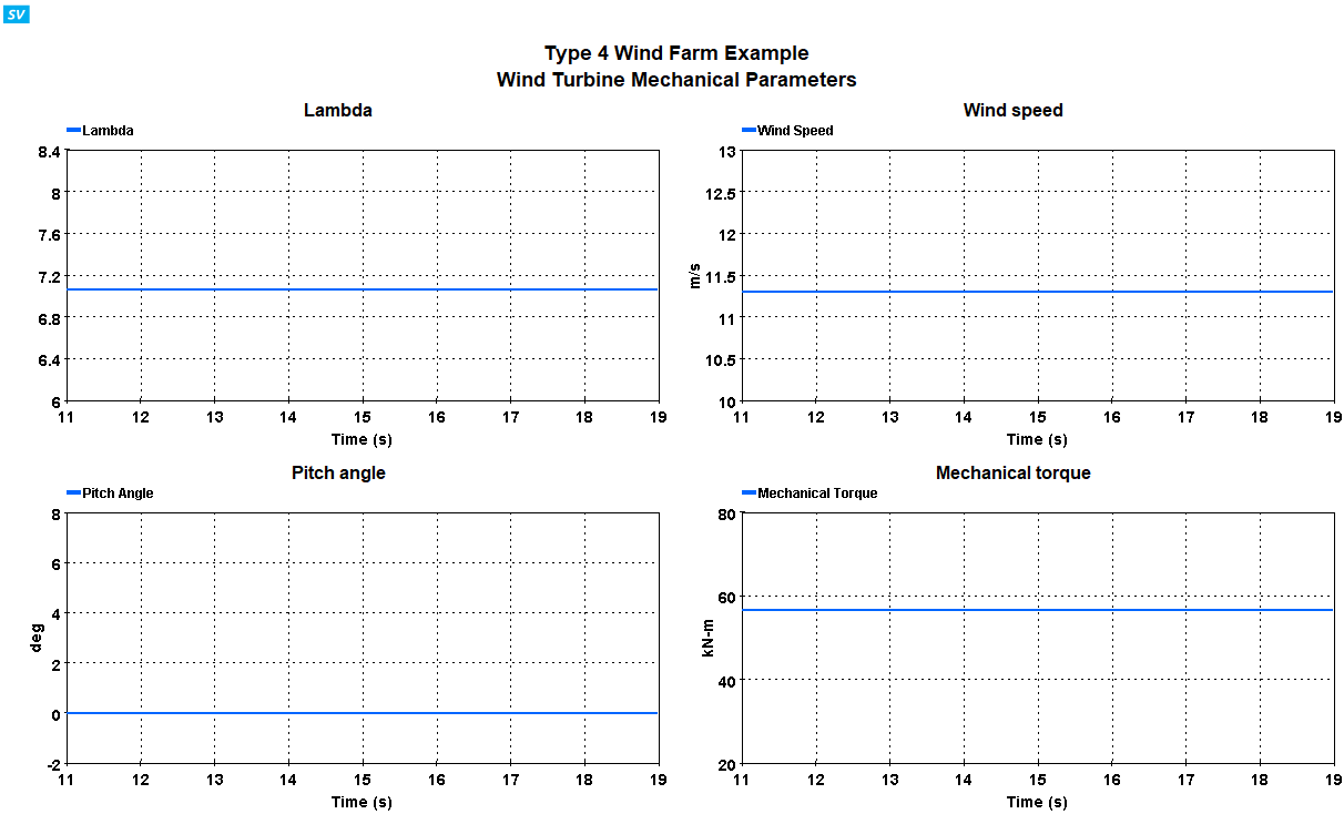
Case 1: Nominal Wind speed: 11.3 m/s
This case shows the performance on the model for nominal wind speed of 11.3 m/s. To execute this case, open the file: “Type4_WindTurbine_33kV.ecf”, and start simulation. To view results, open the ScopeView template file: “Type4_WindTurbine_33kV.svt”.
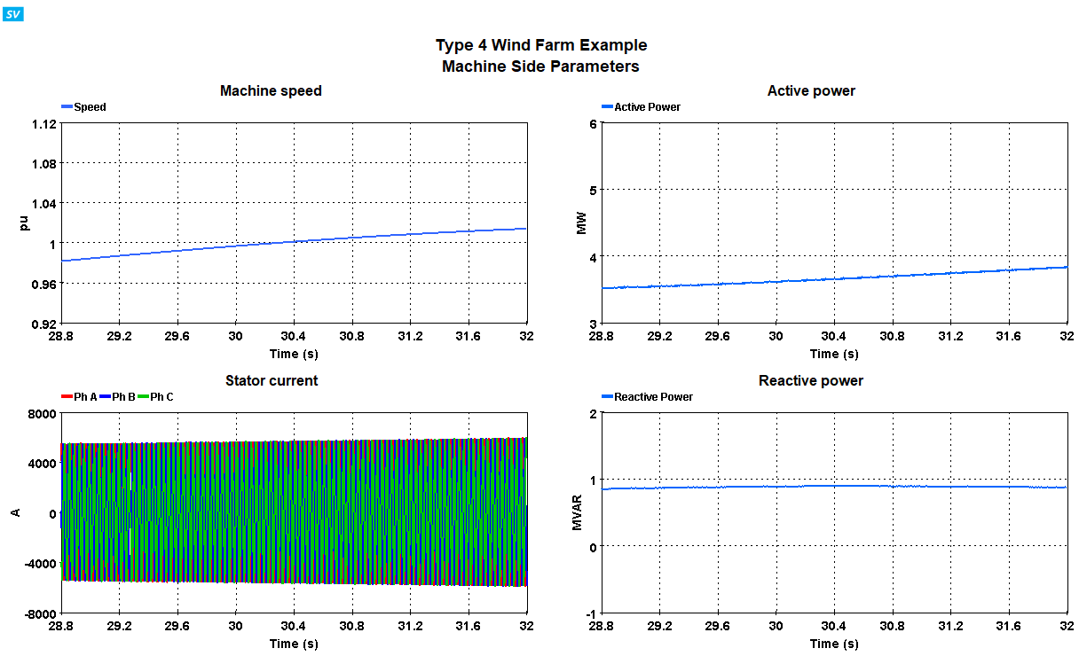
Below figures show the performance of the model. It can be seen that the wind turbine generates 5 .2 MW power as requested.


 As the model represents a wind farm with 10 wind turbine instances, the power to the grid is around 50MW.

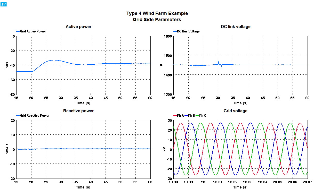
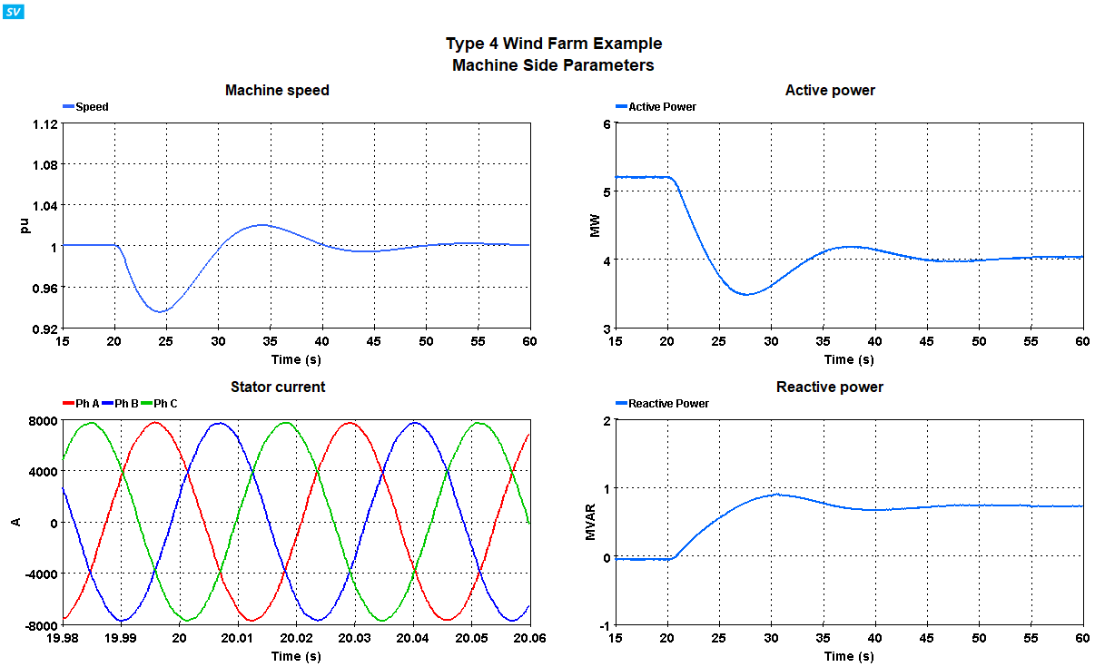
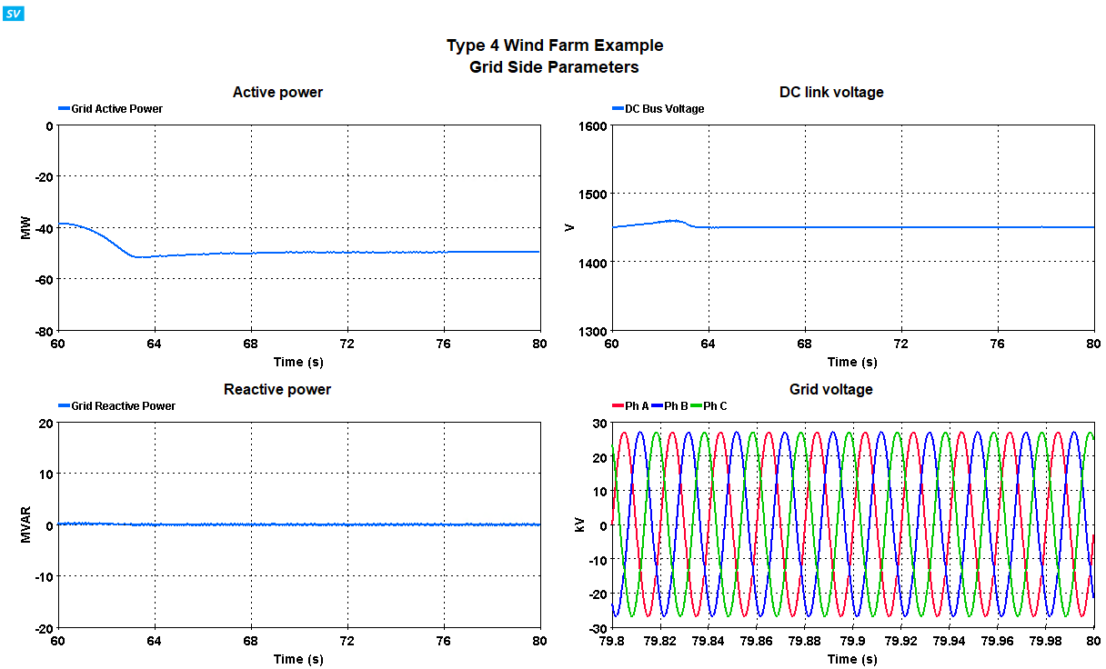
Case 2: Wind speed decrease
This case demonstrates a step decrease in the wind speed by 10%. To execute the test case, open the file “Type4_WindTurbine_33kV.ecf” and edit the gain in the wind speed change logic circuit, as shown in figure below to have a value of -1.13.

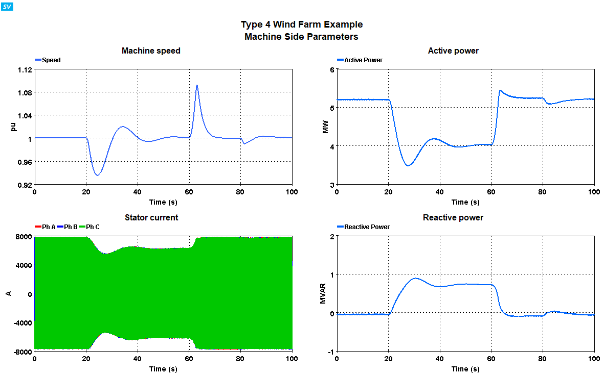
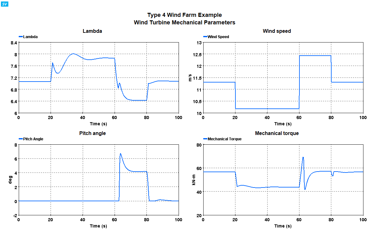
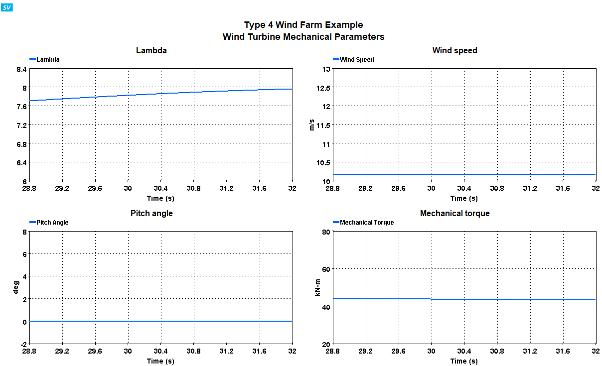
The decrease in the wind speed cause the tip speed ratio of the wind turbine to change. This causes the load torque of the wind turbine to change (as seen in Figure below). The rotor speed reacts to this torque change with the speed temporarily increasing. The speed control loop reacts to this by decreasing the power extracted from the generator. Figure below also shows that the power sent to the grid also decreases (to 0.83pu) due to the less power availability available from the wind. It can be observed that the dc link voltage is regulated well despite the step change in the wind speed.


Case 3: Voltage sag
This case demonstrates a scenario where a that results in a 5% voltage sag in the input voltage for 1s (50 cycles). To execute the test case, open the file “Type4_WindTurbine_33kV.ecf” and open the properties for the programmable AC source AC1 as shown below. The status should be enabled, and then the AC ramp/step should be enabled, with the amplitude set at 0.95*Vbaseph Vbase and the timing is set such that the grid voltage drops to 0.95pu at 30s and gets back to 1pu at 31s.

The Wind farm keeps operating with unity power factor and does not participate in voltage support as expected. The speed and power control keeps the speed and power regulated at their rated values. The voltage at the PCC is shown in below with the voltage sag occurring for 1s, while current at the transformer primary shows the increase in the current in response to the sag to keep the power sent to the grid at rated value and keeping the DC link voltage regulated.


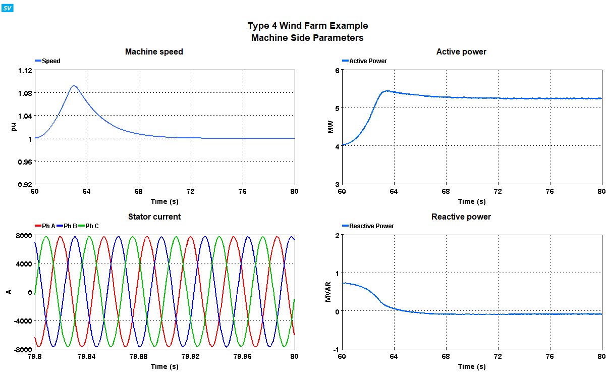
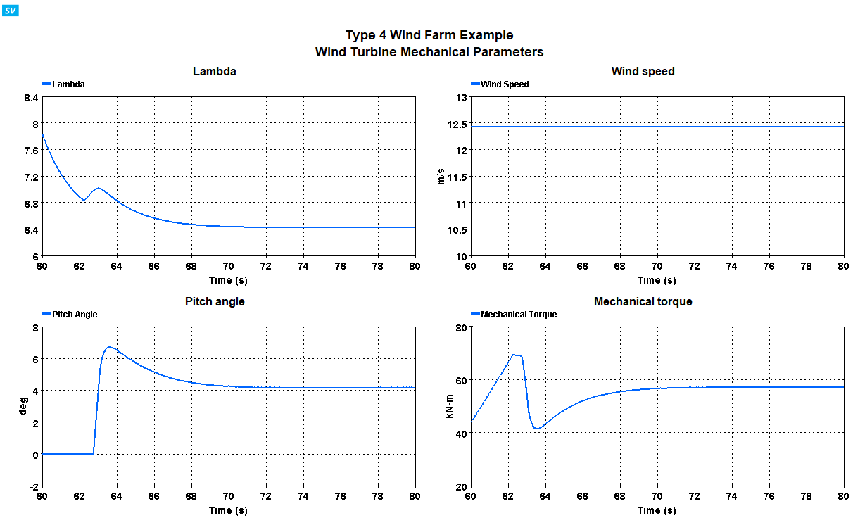
Case 4: Wind speed increase
This case demonstrates a step increase in the wind speed by 10%20%.
The increase in the wind speed cause the tip speed ratio of the wind turbine to change. This causes causes the load torque of the wind turbine to change (as seen in Figure below). The rotor speed reacts to this torque change with the speed temporarily increasing. The speed control loop reacts to this by increasing the power extracted from the generator. Since the operation at a power more than nominal cannot be sustained, the pitch control loop reacts by increasing the blade pitch angle as seen below. This reduces the power extracted from the wind. It can be observed that the dc link voltage is regulated well despite the step change in the wind speed.


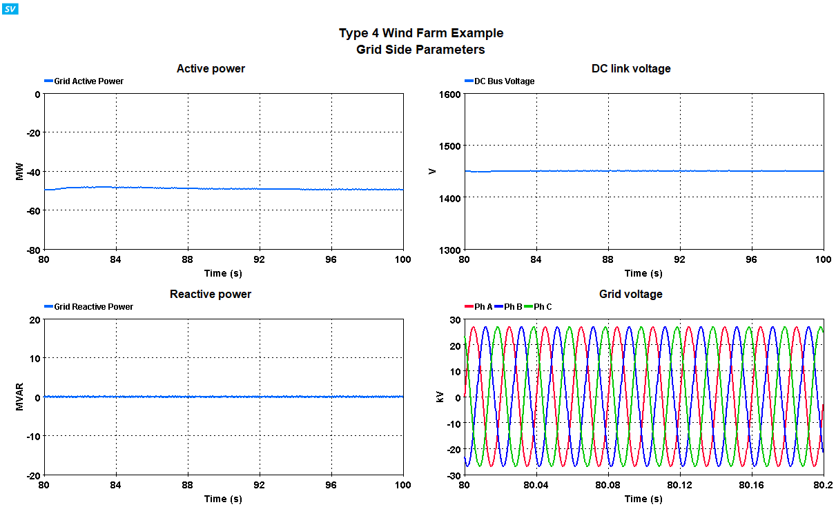
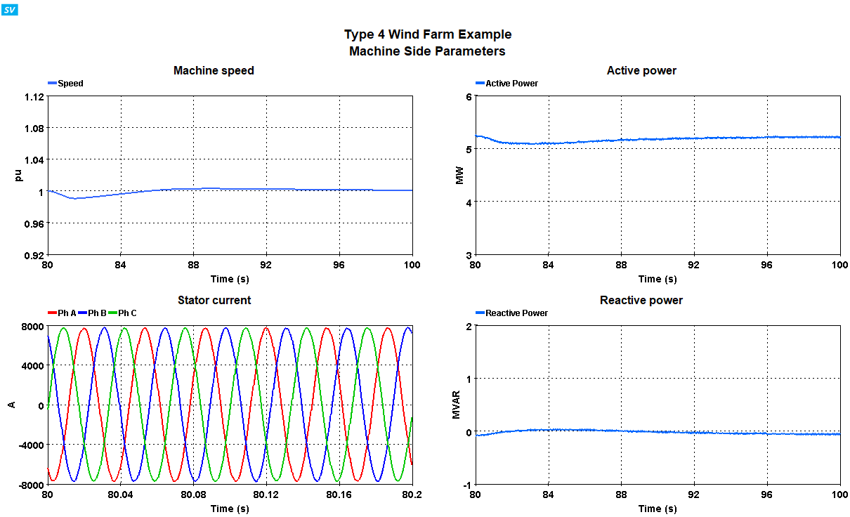
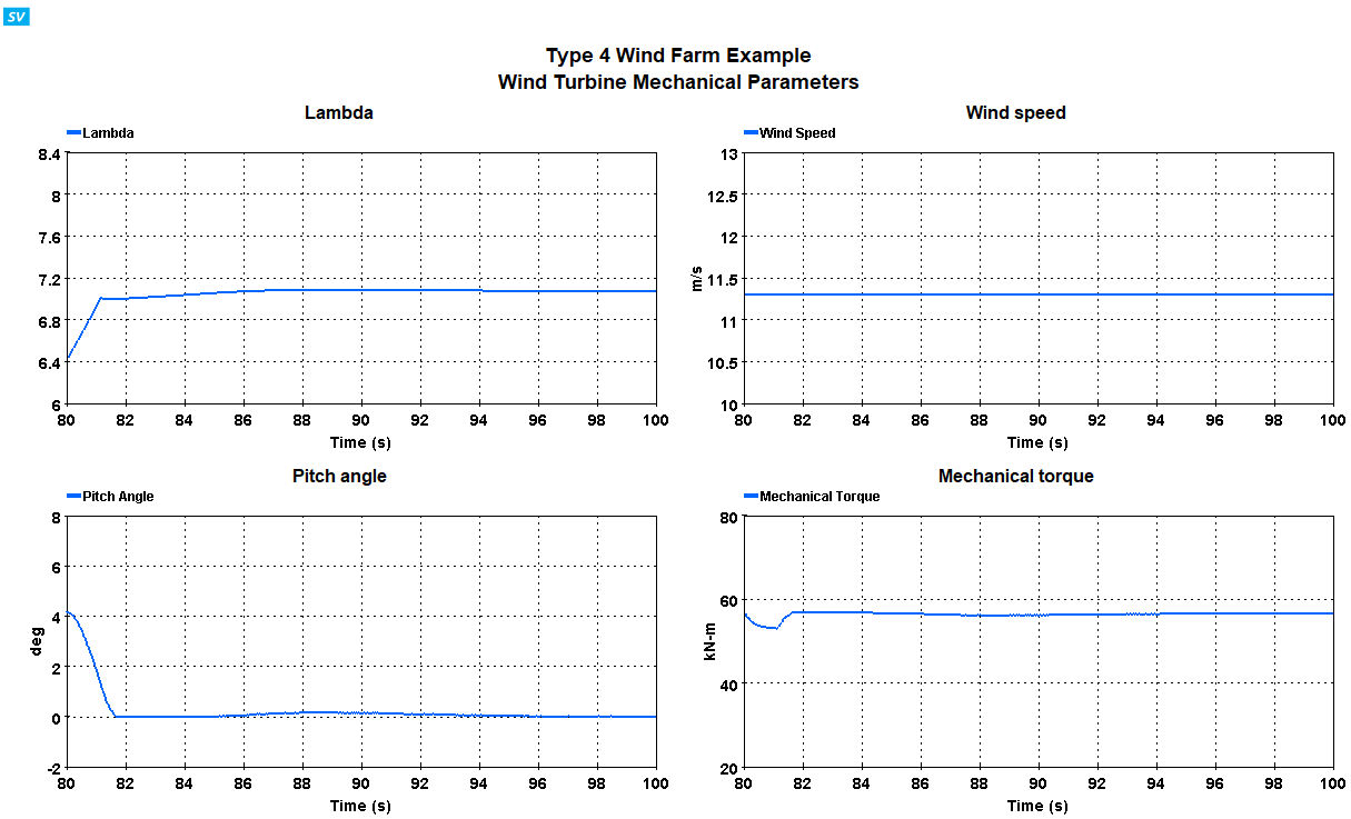
Case 5: Restored to nominal wind speed
This case restored to wind speed to nominal value and prepare the model for next acquisition, this ensures the same results from different acquisition. Since the speed is decreased from 12.43 m/s to 11.3 m/s, the transient response is similar to the wind speed decrease in Case 2 (as seen in Figure below).


References
[1] https://hvdc.ca/knowledge-base/read,article/227/type-4-wind-turbine-generators/v:
[2] K. Clark, N. W. Miller, J. J. Sanchez-Gasca. “Modeling of GE Wind Turbine-Generators for Grid Studies”, April 2010, General Electric International, Inc., NY USA
[3] W. L. Soong and T. J. E. Miller, "Field-weakening performance of brushless synchronous AC motor drives," Electric Power Applications, IEE Proceedings -, vol. 141, pp. 331-340, 1994.