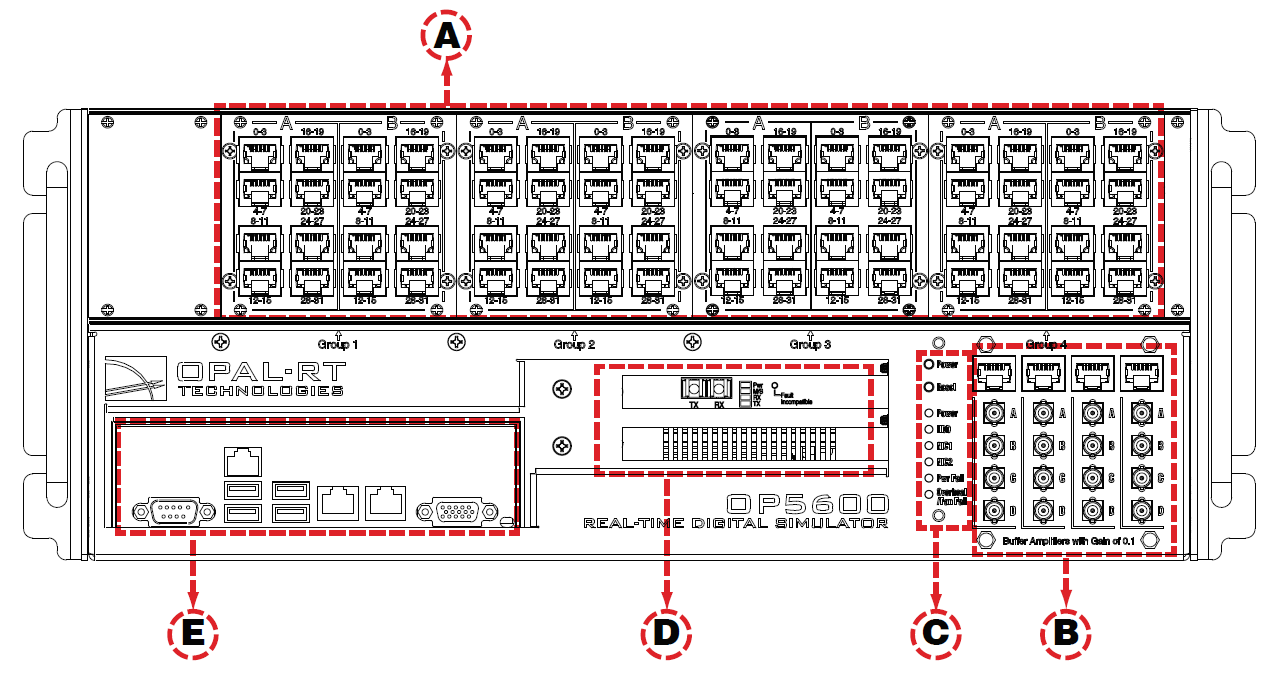
The interfaces on the front of the OP5650 Artix 7 (OP5143) include 4 RJ45 monitoring panels.
A: 4 panels of RJ45 connectors provide connections to monitor output from mezzanine I/O Each connector is linked to front and back mezzanines on the carrier board. Analog mezzanines (channels 0-16) use only the first column of connectors. Digital mezzanines use both columns (channels 0-15 in the first column and channels 16-31 on the second column of connectors). See the mezzanines connector image and the RJ45 pinouts for more detailed information.
B: Monitoring RJ45 connectors with mini-BNC terminals: RJ45 cables connect from a channel on an RJ45 panel (B) to one of four RJ45 monitoring connectors (C). Mini-BNC connectors allow for quick cable connections to monitoring devices (such as an oscilloscope). See OP5650 Connecting Monitoring Devices for details.
C: Target computer monitoring interface. Two push-buttons include POWER in top position to start the Target computer and RESET in the bottom position to reset the Target There are 6 LED indicators:
LED | NAME | Description |
|---|---|---|
Green | Power | On indicates that the unit is powered up. |
Green | HDD | On indicates that the hard disk drive is operating. |
Green | NIC1 | On indicates that network port 1 is in use. |
Green | NIC2 | On indicates that network port 2 is in use. |
Red | Power Fail | On indicates a power fault. |
Red | Overheat/Fan Fail | On indicates either that unit has overheated or a fan fault. |
D: Fiber optic synchronization board (top slot) and optional PCIe connector slot (by default, the lower space is covered by a blank plate if there are no optional PCIe boards).
E: Standard computer connectors (left to right): mouse and keyboard, USB ports, monitor, network ports. Although use of these connectors is optional but not required to use the OP5650, one network port is required for network
