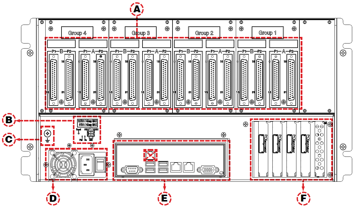
A. DB37F I/O connectors (see OP5700 Pin Assignments for more details). The figure in OP5700 IO Configuration illustrates the links between the mezzanines and the DB37 I/O connectors
B. Power reset and +5/+12 V power source connector (for tests)
- Pushbutton reset after 4A overcurrent shutdown
- Red LED indicates fault, green LED indicates nominal function
- Microfit connector for 5V or 12V power allows users to test whether I/Os are functioning. Each voltage has its own ground reference. Caution: these power sources are not isolated.
C. Ground screw. The OP5700 may be subjected to EMI when it is installed in proximity to other devices. Make sure to connect the OP5700 ground to the rack to prevent any EMI related damage to the simulator (see Figure in OP5700 Connecting Monitoring Devices)
D. Power connector and power On/Off switch.
E. Standard computer connectors (left to right): mouse and keyboard, USB ports, monitor, network ports (see Figure in OP5700 Installation and Configuration).
F. Low-profile PCIe slots3. These slots give access to five of the six PCIe slots. The sixth slot is reserved for the internal connection of the Virtex7 FPGA board.
Refer to the system Description document received with your simulator for a more detailed description of the configuration.
Note: OP5707-4 and OP5707-8 configurations only use one CPU, and can only manage five PCIe slots, leaving 4 slots available for third-party I/O or communication boards.
Note: High-profile PCIe boards or PCI boards must be installed in the front bays of the chassis, and connected to the motherboard using riser boards. Since each riser uses one PCIe slot of the motherboard, the number of slots available at the back of the chassis is reduced. Each riser board can connect two PCI cards.

