Documentation Home Page ◇ HYPERSIM Home Page
Pour la documentation en FRANÇAIS, utilisez l'outil de traduction de votre navigateur Chrome, Edge ou Safari. Voir un exemple.
Examples | Distribution Connected Battery Energy Storage System with Average Converter
Location
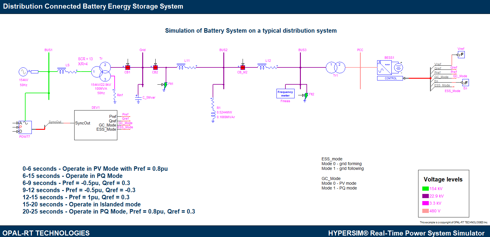
This example model can be found in the software under the category "Renewable Energy" with the file name "Battery_Energy_Storage_System.ecf".
Description
In this example a one stage battery energy storage system (BESS) is modeled. The BESS is connected to a typical distribution system and several scenarios are implemented demonstrating the BESS operation in grid following and grid forming modes. The interface converter of the BESS is an average inverter model.
This model shows the simulation of a 1 MW, 1050 V, 5 MWh battery energy storage system connected, via a feeder, to a simplified 22.9 kV 50 Hz three phase distribution system. The feeders are modeled with their equivalent direct sequence and zero sequence impedances. BUS2 in the model has a load of 0.5244 MW and 0.1669 MVAr connected to it. The load and the BESS can be islanded by opening the breaker CB2.
The BESS is connected to PCC via a 22.9 kV/480 V, 1.2 MVA star-delta distribution transformer. The transformer secondary is connected to the grid side converter with a 440 µH choke filter. The choke filter was designed to limit the total harmonic distortion of the BESS current injected into the grid at 5% for the switching frequency of 1350 Hz (although the inverter used in this example is an average model). The DC side filter was selected to limit the battery current ripple to 5% for the charging mode of operation. The inverter is responsible of controlling the active and reactive power at the transformer secondary.
The block DEV1 creates the stimuli signals to execute the sequence of events demonstrating the operation of the BESS.
For more details about the BESS model please refer to Battery Energy Storage System (BESS) - Average.
Simulation and Results
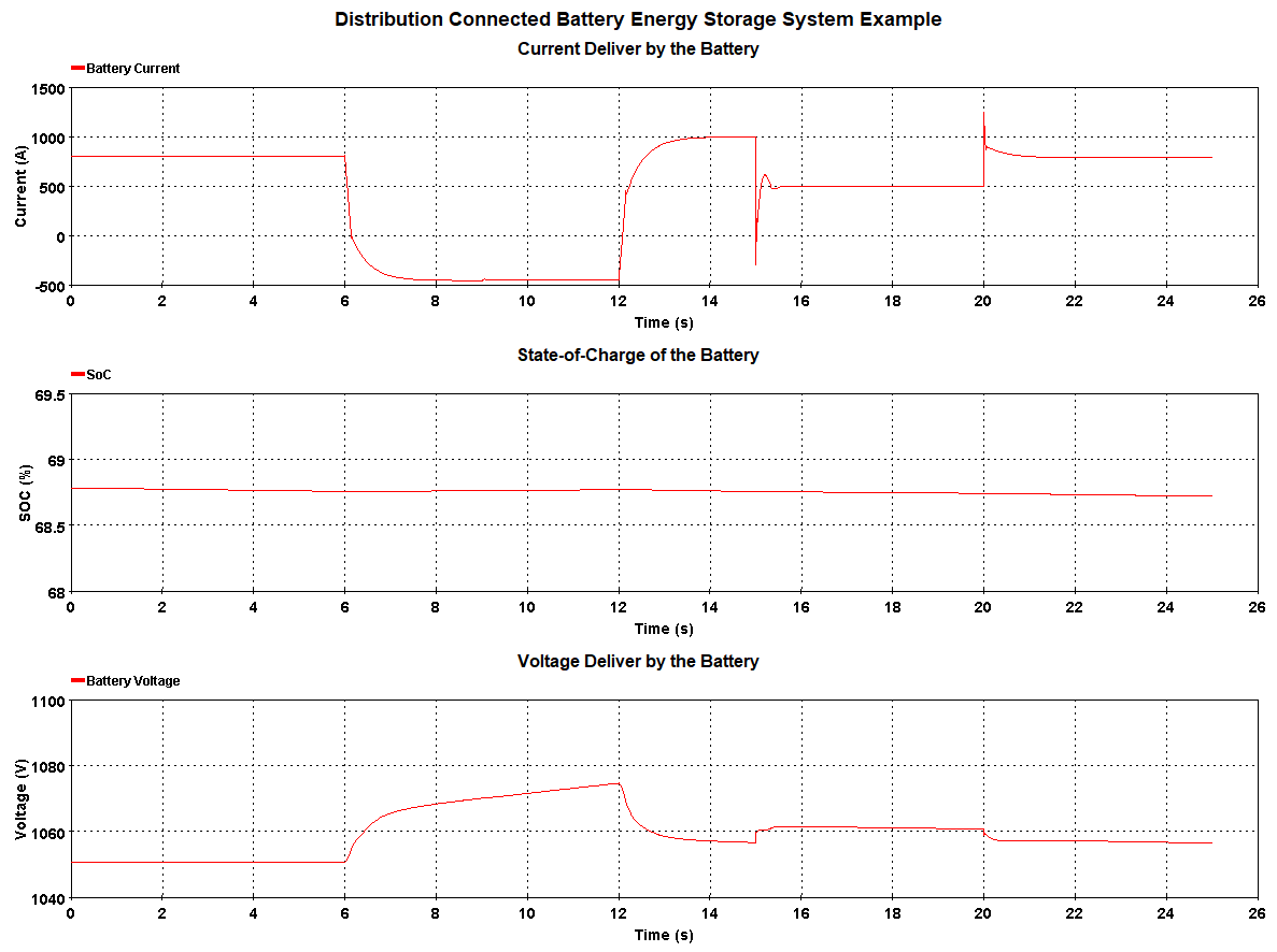
The demonstration tests all the modes of BESS operation mentioned in Battery Energy Storage System (BESS) - Average. The results are shown in the figure below. The sequence of the mode change is shown in the next table. The model was tested at a time-step of 50 µs.
| From | To | Mode | Pref (pu) | Qref (pu) |
|---|---|---|---|---|
0 s | 6 s | PV | 0.8 pu | Voltage Regulator |
6 s | 9 s | PQ | -0.5 pu | 0.3 pu |
9 s | 12 s | PQ | -0.5 pu | -0.3 pu |
12 s | 15 s | PQ | 1 pu | 0.3 pu |
15 s | 20 s | Grid Forming | - | - |
20 s | 25 s | PQ | 0.8 pu | 0.3 pu |
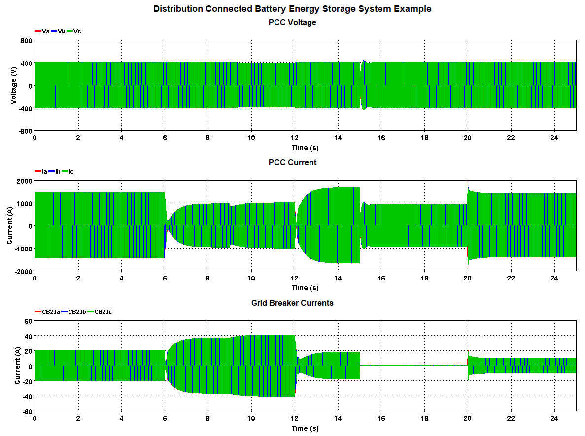
The results show that in the first period, when the BESS operates in PV mode, the BESS Voltage regulator tries to reduce the voltage from 1.01 pu to 1 pu, however, since the voltage is set by the grid, the BESS has limited influence on it and therefore keeps increasing the magnitude of Qref.
From 6s to 15s the BESS operates in PQ mode and follows different active and reactive power references as defined in the table. It should be noted that from 12-15 s when Pref=1 pu and Qref=0.3pu, the active power follows its reference, however, the reactive power is reduced to zero to respect the converter ratings while prioritizing active power.
At 15s the breaker, CB2 opens and remains open till 20s. The BESS is also switched to grid forming mode at this time. We can see that the PCC voltage starts to fall but is again regulated to 1 pu by the BESS. During this period the active and reactive power references are ignored, and the P and Q provided by the BESS is equal to the two loads connected to BUS2. The figure shows that the islanding breaker has no current flowing through during the islanded period. The frequency of the system is also maintained at 50 Hz throughout the operation as shown in the figure.
At 20s, CB2 is closed and the BESS is brought back into PQ mode following the active and reactive power references as provided in the table.

References
[1] J. Rocabert, A. Luna, F. Blaabjerg and P. Rodríguez, "Control of Power Converters in AC Microgrids," in IEEE Transactions on Power Electronics, vol. 27, no. 11, pp. 4734-4749, Nov. 2012.
doi: 10.1109/TPEL.2012.2199334
[2] Amirnaser Yazdani and Reza Iravani. Voltage-Sourced Converters in Power Systems: Modeling, Control, and Applications. John Wiley & Sons Inc, 2010.
OPAL-RT TECHNOLOGIES, Inc. | 1751, rue Richardson, bureau 1060 | Montréal, Québec Canada H3K 1G6 | opal-rt.com | +1 514-935-2323