This chapter explains the steps required to use the BERTA Certification application with the TestDrive software. The certification principles, the hardware components and the software used are described.
Certification Principles
BERTA Certification lets you check the technical characteristics of a speed governor in test conditions. You can test the control system or a programmable controller in the case of a digital speed governor. The controller generates signals for the servomotors based on set points or speed variations received from the AC generator.
The speed governor controls the following:
- AC generator rotation speed.
- Power operating point or at gate opening.
The programmable controller is designed to control these three operating modes:
- Idle running at startup or stoppage.
- Idle running in synchronous network.
- Islanded grid running.
BERTA Certification can simulate these three operating modes.
For more details on how to start the application and use its interface, refer to the General Introduction chapter.
Certify_1 Button
The Certify_1 button provides access to four graphic display panels (one panel per dial) and two control panels (Indicators and Calibration).
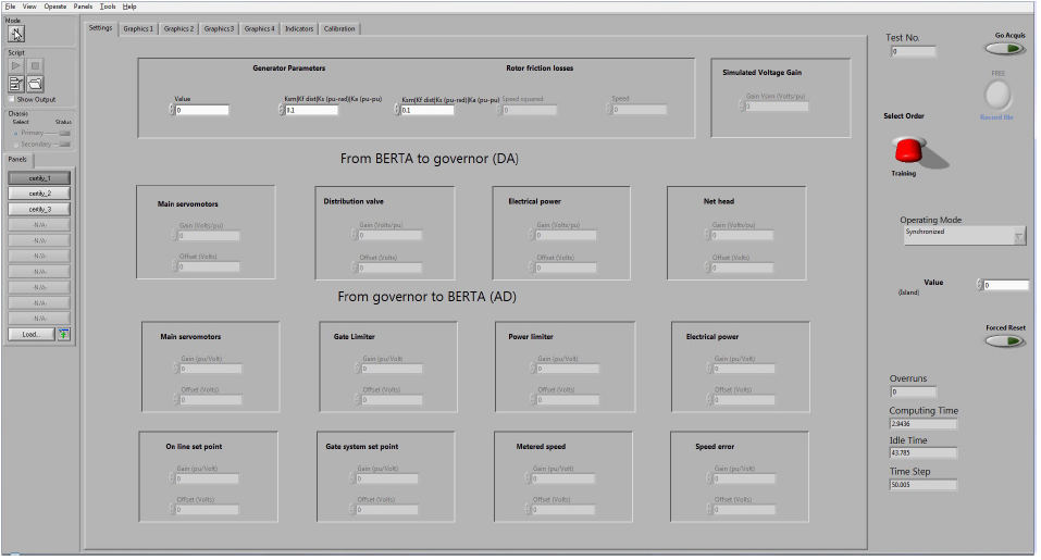
Settings Panel
Click the Settings tab to set the following parameters:
- AC generator simulation.
- Conversion into volts of voltage signal generated by BERTA.
- Conversion into volts of BERTA digital signals sent to speed governor.
- Conversion into digital values of speed governor analog signals sent to BERTA.
Set all the parameters following the simulation requirements. These parameters can be saved to a file and automatically assigned at the start of the next simulation. See Stopping the simulation in the General Introduction chapter for instructions on how to save current simulation parameters or return to default settings.
Graphic Panels
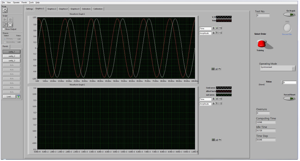
Graphics 1 to Graphics 4 tabs display the corresponding panels with graphs and have the same interactive menus. Only the signals displayed are different. Accordingly, only Graphics 1 panel will be shown.
Range values and coordinate labels can be changed quickly to meet the simulation needs.
Graphics 1 Panel
| V_FO | Speed (rated frequency 60Hz) |
|---|---|
| Vsim | Speed simulated by BERTA |
| Cd servo | Command servo (setting launched by the Certify_2 control panel) |
| DXref Berta | Servo motors’ reference position (user-defined parameters) |
| Out servo | Servo motors’ output signal |
Graphics 2 Panel
- Displays the same results as Graphics 1 panel, but with a larger scale.
- Displays the output signal of resulting speed.
Graphics 3 Panel
- Not used presently. User can display a signal of his choice here.
Graphics 4 Panel
| D speed | turbine speed variations |
|---|---|
| Out servo | servomotors output signal |
| Pmec | turbine mechanical power |
| Pelec | AC generator electrical power |
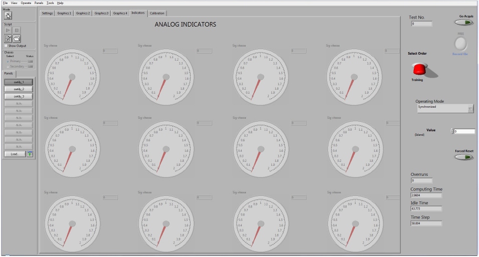
Dials Panel
Clicking the Dials tab displays the analog dials. Data shown in this panel are not recorded.
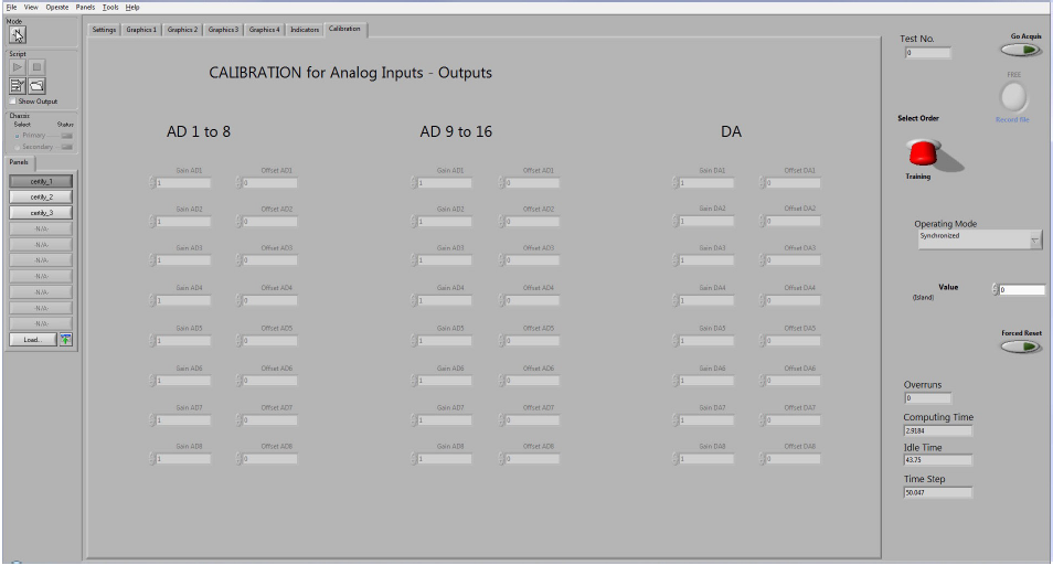
Calibration Panel
Clicking the Calibration tab displays the analog input/output calibration panel. Make sure the AD and DA calibrations are set to the desired values. These values are factory-configured to compensate for minor errors in the analog/digital or digital/analog converters and do not require frequent adjustments.
Certify_2 Button
The Certify_2 button provides access to five control panels, four of which display functional diagrams for the models programmed in the test bench, with active buttons and switches.
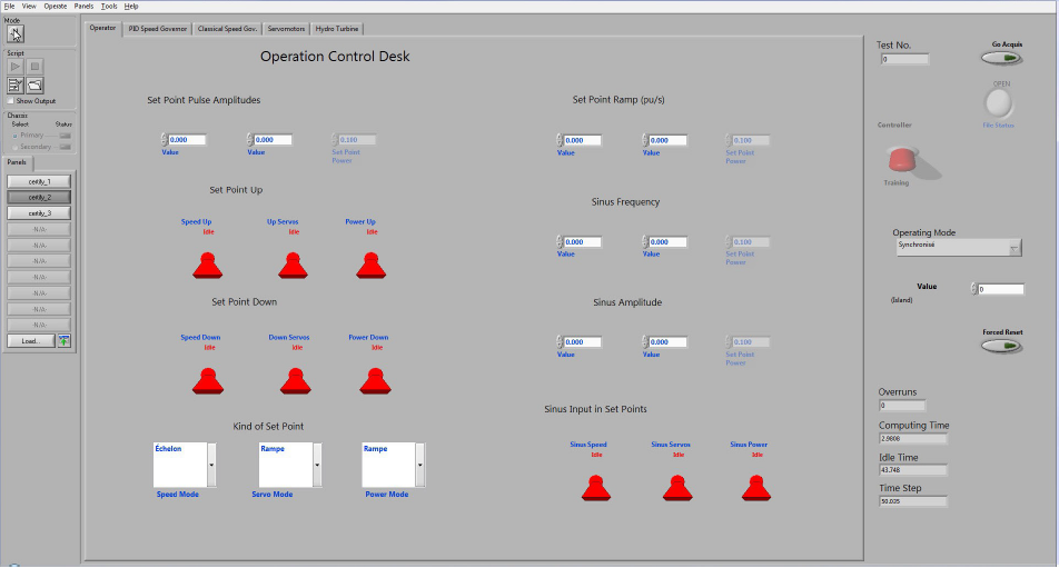
Operation Control Desk
This panel is used to send commands to the training speed governor programmed by the BERTA test bench algorithm. All the buttons are available to change simulation commands and parameters.
- This panel is only available if the Training selection is activated. It controls operations while in Training mode.
- This panel lets you provide settings for the application’s internal speed governor.
- It is possible to change the setpoint amplitudes. Hence, changes in the controlled speed, position or power will be made with a bigger or smaller disturbance, according to the selected amplitude.
- There are three possible setpoint types: Step, Ramp or Sinus. Buttons on the left of each field are used to configure setpoint values.
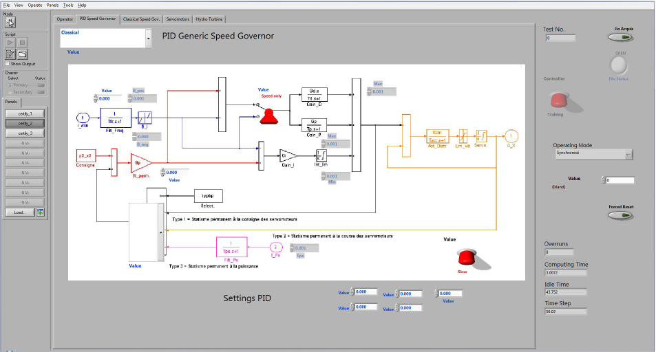
Generic PID Speed Governor Panel
The figure below shows a generic PID type speed governor model. The diagram displayed contains buttons to change the generic PID speed governor parameters.
Note: This panel is only available if the controller is in Training mode.
The PID type switch lets you select the speed governor’s control mode:
| Red | Only the speed error signal attacks the derived and proportional gains. The correction signal from the permanent droop only attacks the integral gain. |
|---|---|
| Green | The speed error signal and the correction signal from the permanent droop attack the three gains: proportional, integral and derived. |
The load pick-up switch, in the lower right corner, lets you activate load pick-up acceleration:
| Red | Load pick-up acceleration is inactive. Load pick-up, or the response to a change in operation set point, is slow. |
|---|---|
| Green | Load pick-up acceleration is active. The setpoint signal goes through an acceleration function that converts instantly the servomotors’ position control signal. |
Speed governor gain and constant adjustments can be accessed directly using the buttons in the diagram.
- Permanent droop (Bp) is added to activate the servomotors increase set point. This means that the operator changes the servomotors increase setpoint using the Hausse_servo button on the control panel and will then change the speed governor’s permanent droop value to activate the set point.
- The selector offers three options:
- Type 1: Permanent droop in servomotors set point.
- Type 2: Permanent droop in servomotors stroke.
- Type 3: Permanent droop in power.
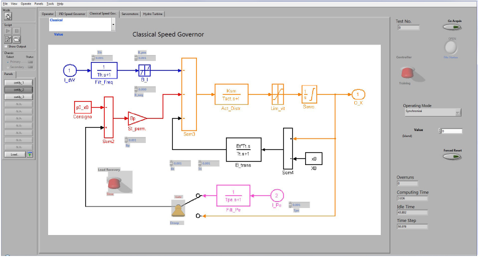
Classical Speed Governor
The figure below shows a classical speed governor model. The diagram displayed has buttons to change the classical speed governor parameters.
Note: This panel is only available if the controller is in Training mode.
The Bp type switch lets you select the origin of the permanent droop:
| Red | Servomotors stroke. The setpoint is for an electrical opening. |
|---|---|
| Green | Power set point. |
The Load pick-up switch lets you accelerate the load pick-up:
| Red | Acceleration inactive. Load pick-up, or the response to a change in operating point set point, is slow. |
|---|---|
| Green | Load pick-up acceleration is activated. The setpoint signal goes through the acceleration function to converts instantly the servomotors position control signal. |
Speed governor gain and constant adjustments can be accessed directly using the buttons in the diagram.
Servomotors Panel
The speed governor hydraulic chain represents the main servomotors that open or close gates and the two amplification circuits comprised of the actuator and the distributor (Figure 61).
Note: The servomotors model is an important part of the Certification application because it functions in two modes: Training or Actual speed governor.
The hydraulic chain’s reaction lets you validate the functions of the programmable controller.
Three switches allow to adjust the operating modes of the hydraulic chain:
- The Feedback Dist. switch lets you adjust the distributor feedback configuration according to the feedback signal from the programmable controller (green) or the application’s internal model’s gain output “Kf”.
- The Feedback Servomotors switch lets you adjust the servomotor feedback configuration according to the feedback signal from the programmable controller (green) or directly from the application’s internal model.
- The Table or Ksm switch that lets you select the mode representing the servomotors operating speed; either a function table or a fixed gain (Ksm).
Gain and time constant adjustments are displayed at the bottom of the panel (Figure 61).
Gain in p.u. per volt and feedback signal offsets in volts from the real governor’s programmable controller are adjustable in the Feedback distributor and Servomotors feedback sections of the panel.
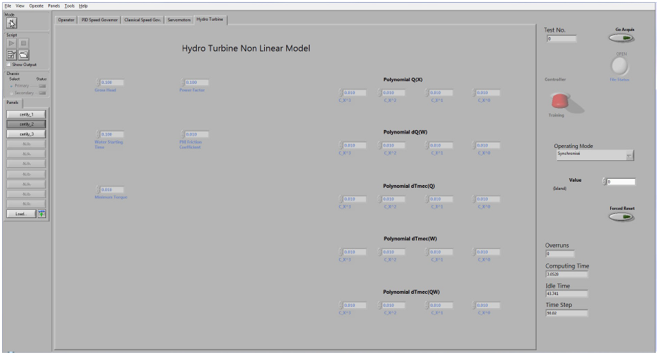
Hydraulic Turbine Panel
This panel lets you adjust the non-linear hydraulic turbine’s parameters.
Note: This panel also functions in two operating modes: Training and Actual Speed Governor.
| Flow polynomial Q(X) | Q= C2X2+C1X1+C0X0. This polynomial represents the relationship between the flow and the servomotor stroke. |
|---|---|
| Flow variation polynomial dQ(w) | dQ= D2ω2+D1ω1+D0ω0. This polynomial represents the relationship between the flow variation and the turbine rotation speed. |
| Mechanical torque variation polynomial dTmec(Q) | dTmec= E2Q2+E1Q1+E0Q0. This polynomial represents the relationship between the mechanical torque variation generated by the turbine and the flow, according to the mechanical torque equation given below. |
| Mechanical torque variation polynomial dTmec(w) | dTmec= F2ω2+F1ω1+F0ω0. This polynomial represents the relationship between the mechanical torque variation and the rotation speed, according to the mechanical torque equation given below. |
| Mechanical torque variation polynomial dTmec(Qw) | dTmec= G2Q2ω2+G1Q1ω1+G0Q0ω0. This polynomial represents the relationship between the mechanical torque variation and the product of flow by speed, according to the mechanical torque equation given below. The equation for the mechanical torque is the following: Tmec = Tmx [ 1+ dTmec (Q) + dTmec (w) + dTmec(Qw)] where Tmx represents the mechanical torque depending on the servomotors opening and the net available head. |
Certify_3 Button
The Certify_3 button provides access to two control panels and two graphic panels.
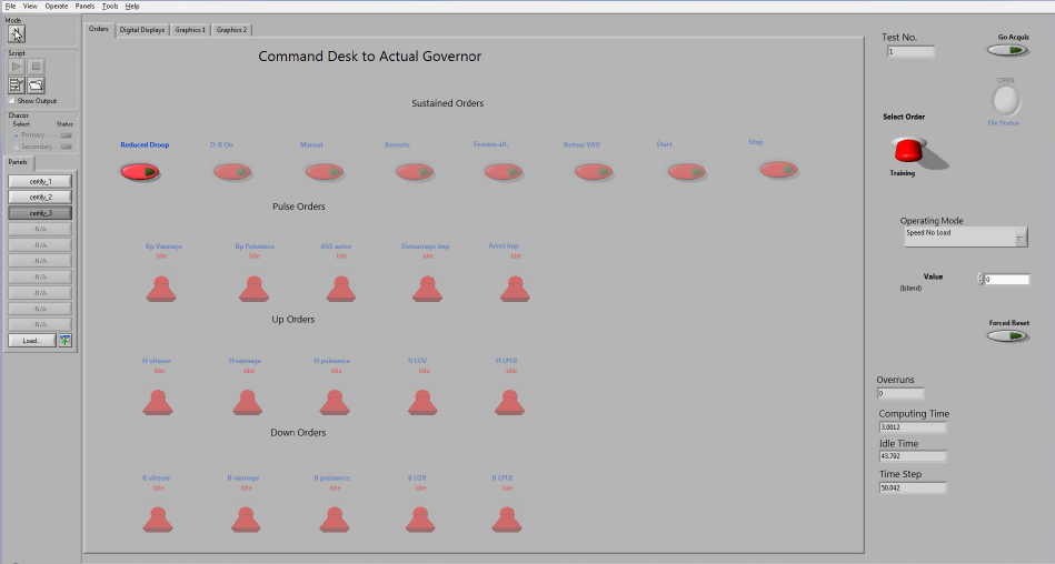
Command Desk to Actual Speed Governor Panel
This panel lets you transmit command signals to the actual speed governor. The panel reproduces roughly the actual operator console in a power plant.
The buttons in the two top rows are used to send commands from the operating mode to the actual speed governor. These settings are activated when the button is pressed and deactivated when the button is pressed a second time.
These command buttons will generate digital signals for the following outputs:
- Reduced droop, = reduced droop
- D-B On = dead band in service.
- Manual = manual mode
- Remote = remote mode,
- Tension alt. = presence_V,
- VAV return = vav_return.
- Start •
- Gate actuation = gate_act
- Power actuation = ass_puiss,
- Free = other_ass,
- Pulse start = start_impuls,
- Impulse stop = stop_impuls,
- Speed up = h_vit,
- Gate up = h_van,
- Power up = h_puiss,
- LOV up = h_lov,
- LPUI up = h_lpui,
- Speed down = b_vit,
- Gate down = b_van,
- Power down = b_puiss,
- LOV down = b_lov, • LPUI down = b_lpui.
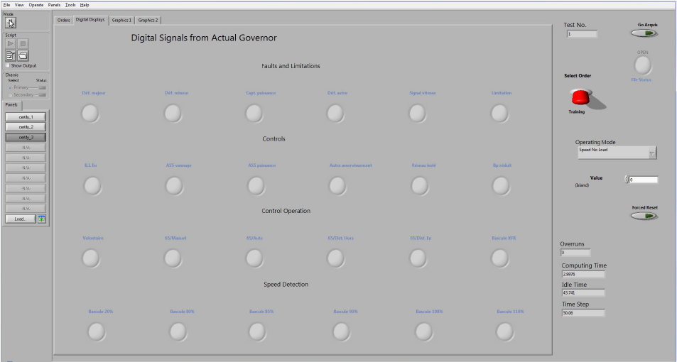
Digital Signals From Actual Speed Governor Panel
This panel corresponds to acquisitions from acq_3. It displays status detection signals from the actual speed governor.
Graphic Panels
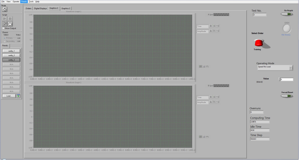
Graphics 1 and Graphics 2 tabs display the corresponding panels with graphs and have the same interactive menus. Only the signals displayed are different. Accordingly, only Graphics 1 panel will be shown.
Graphics 1 Panel
- The top monitor displays:
- Pmec: Turbine mechanical power.
- Pelec: AC generator electrical power measured by the voltage sensor.
- The lower monitor displays:
- The monitor does not display anything. User can display a signal of his choice here.
Graphics 2 Panel
- Neither monitor displays anything. User can display a signal of his choice here.
| Operating Mode | Description |
|---|---|
| Speed No Load | The No Load operating mode simulates rotation speed without electrical current. The mechanical torque applied by the turbine feeds the rotor. The resisting torque is determined solely by friction loss. A simple model lets you define the torque according to the rotation speed. It should be noted, however, that the mechanical torque applied by the turbine is also dependant on rotation speed. |
| Synchronized | In synchronous network mode, resistance to mechanical torque is comprised of friction resistance torque and electrical torque, which is the sum of synchronization and damping torques. These torques typify the reaction of the network synchronized AC generator to changes in operating conditions. The synchronization torque determines the natural frequency of a synchronized AC generator’s power oscillations. It is highly dependent on drive power. The damping torque is generally low when the voltage speed governor is not equipped with a stabilizing circuit. The diagram describes the equations that let you calculate synchronization and damping torques according to the natural oscillation frequency FN and the damping factor. |
| Islanded Operation | In Islanded operation, the friction resistance torque and the total electrical load for the Islanded counter the mechanical torque. The total load is comprised of the initial power generated in the previous operating mode and a range defined in the operating mode control panel. This range comes into effect when in Islanded operation or when its value is changed while in Islanded operation. |
