Documentation Home Page ◇ Hardware Home Page
Pour la documentation en FRANÇAIS, utilisez l'outil de traduction de votre navigateur Chrome, Edge ou Safari. Voir un exemple.
OP7832 Synchronization Board
- Sylvain Ménard
The OP7832 provides connection interfaces for OPAL-RT’s hardware synchronization signal. This signal is used to synchronize the calculation time steps of several chassis and real-time simulators in distributed simulations.
The OP7832 is compatible with OP7000 and OP7000V2 chassis.
It supports the standard hardware synchronization signal shared by most OPAL-RT products and is compatible with older systems (using legacy synchronization signal on copper cables) and newer systems (supporting a composite synchronization signal propagating on plastic optical fibers or HD15 copper cables).
The board can receive or output the synchronization signal depending on the Primary FPGA synchronization mode (Master or Slave) programmed in the real-time simulation.
It also features :
- 8 status LEDs,
- 2 rotary switches used to define the Chassis ID of the unit,
- on-board switches used to configure the active Rx/Tx connectors (copper stereo jack, optical transceivers or HD15 connectors).
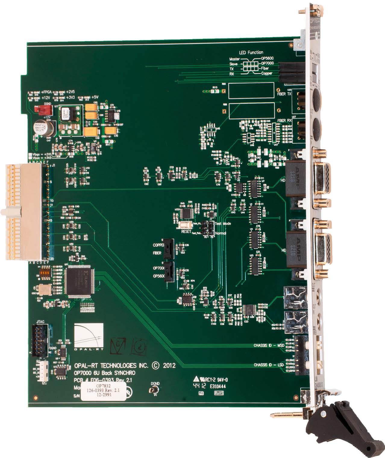
Board Layout

The connectors and switches are described in the following sections. Note however these features:
- the push button switch SW6 is a reset switch. It is reserved for OPAL-RT technicians use only.
- Located next to the reset switch, jumper P5 defines whether the board is in Normal or Test mode. This jumper is factory configured to the appropriate setting. Changing this jumper setting may damage the board.
- JTAG and I2C connectors are used for factory configuration and reserved for OPAL-RT technicians use only.
Operation modes
Legacy mode
This mode, compatible with most OPAL-RT platforms, from the older Wanda box and HILbox to the OP5707, is used to propagate a short synchronization pulse between several systems, in order to synchronize the beginning of their CPU calculation step, and trigger I/O sampling simultaneously on their internal I/Os and the I/Os of all expansion chassis connected to them.
The link operates in daisy-chain, by cabling successively the OUT jack of one unit with the IN jack of the following one. The first unit of the chain is identified as the Master of the synchronization link and the other units as Slaves.
This mode uses copper cables and the stereo jack connectors of the OP7832 card.
Composite mode
In this more advanced mode, the legacy synchronization signal is superimposed with another pulse train, which is aligned to an inner-FPGA calculation step. This mode is supported only by newer OPAL-RT products, like OP7000, OP7020 , OP5607, OP45xx, OP5707, OP4200. Support for OP5600 and OP5650 is availab;e with an add-on card. This mode allows high precision multi-FPGA simulations to be distributed between several chassis.
The composite mode typically uses plastic fiber optic cables and Avago Rx/Tx transceivers. Like with the legacy mode, the link operates and must be cabled in daisy-chain between all units participating in the distributed simulation.
Alternatively, the OP7000 chassis also supports this composite mode on copper cables with HD15 connectors. This cabling option can only be used between different OP7000 chassis.
Mix of legacy and composite mode
The switches features of the OP7832 card make it possible to use a combination of legacy mode and composite mode : for example the synchronization link of an OP5600 system can be connected to the IN stereo jack connector of an OP7000 and this OP7000 can output the synchronization signal in composite mode on its OUT HD15 connector. This mode allows to take advantage of the higher precision of the composite mode of synchronization for distributing simulation of two or more chassis, while maintaining compatibility with older systems.
Synchronization of multiple FPGA in the same OP7000 chassis
Although the Primary FPGA of and OP7000 or OP7000V2 chassis is set in Master or Slave mode based on the real-time simulation and synchronization cabling configurations, the Secondary FPGAs installed in a chassis are automatically configured as Slaves of their Primary FPGA and operate in composite mode. No extra connection is required to achieve this synchronization of all the FPGA cards installed in one chassis, since the synchronization signal is propagated on the mid-plane of the chassis.
Installation
The OP7832 synchronization module must be inserted at the back of the OP7000 or OP7000V2 chassis, in the central slot (F2, red rails). Refer to the schematic on page OP7000V2 Adding or Replacing Boards for locating this slot.
Make sure that the board is properly aligned using the guide tracks before pressing the module into place.
Front Plate
The front interface gives access to the Rx/Tx synchronization signal connectors, the two rotary switches, and 8 status LEDs.
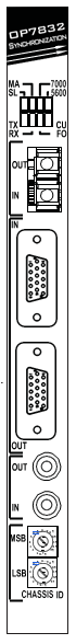
Status LEDs
These 8 LEDs indicate the status of the different functions of the board:
Function ID | Function Name | Description | |
SL | SLAVE | ON means all FPGAs in the chassis (Primary and secondary boards) are in Slave Mode |
|
MA | MASTER | ON means that the Primary FPGA of the chassis is in Master Mode (1) | |
5600 | OP5600 | ON, in a multi-chassis system, indicates that the SYNC input signal comes from one OP5600 or other legacy-compatible chassis, on the stereo jack connector. | |
7000 | OP7000 | ON, in a multi-chassis system, means that the SYNC input signal comes from one OP7000 chassis on the HD15 connector. | |
TX | TX_ACTIVE | ON means SYNC pulses are produced on the active OUT connector | |
RX | RX_ACTIVE | ON means SYNC pulses are received at the active IN connector | |
CU | CU | ON means that the active connectors are the In/Out HD15 or audio connectors | |
FO | FO | ON means that the active connectors are the In/Out optical fiber connectors | |

In the case of synchronization with a single OP7000, even configured as a Slave, the Master LED remains on despite everything, because the OP7000 must regenerate the combined synchronization pulse for other possible OP7000s to be synchronized.
The first LED will always be MASTER ON, and the others will have their SLAVE LEDs on.
Connectors
The first three connectors determine which of three (3) types of synchronization is used. Each connector is linked to two switches on the board, as shown in the table below. The last connector lets users select a chassis ID.
| Connector type | Description | Connector | Switch settings |
|---|---|---|---|
| Fiber Optic transceivers | These transceivers are used to output or receive the synchronization signal when the switches are set to FIBER and OP7000. They are used to synchronize two or more OP7000 chassis in the same real-time simulation. The Avago AFBR-2624Z/1664Z 650nm transceivers are compatible with 1mm Plastic Optical Fibers with Versatile Link connectors, up to 50m long. Using these connectors and fibers provides better reliability over long distances than the HD15 connectors with copper cables. |
|
|
| HD15 | These connectors are used to output or receive the synchronization signal when the switches are set to COPPER and OP7000. These are standard HD, pin to pin connectors. They are used to synchronize two or more OP7000 chassis in the same real-time simulation. The typical cable used with this connector is HD15 M/M 6’ High-Resolution Coax VGA Cable (OPAL-RT P/N: T00-1845). |
|
|
| Stereo Jack | These stereo jack connectors are used to output or receive the synchronization signal when the switches are set to COPPER and OP5600. They are used to synchronize the OP7000 chassis with other OPAL-RT units compatible with this type of link such as: OP56xx systems, OP4510/OP4520, OP5707. The typical cable reference for use with these connectors is AUDIO CONN CABLE ASSY 3.5MM M/M 6FT (OPAL-RT P/N : T00-0824), but longer cables can be ordered for inter-chassis distances of up to 30m (100ft). |
|
|


Note that the switches configuration will usually be factory set and the proper connector/cable pair recommended by OPAL-RT according to the customer's whole system specifications.
When replacing a defective OP7832 board, make sure to set the switches exactly as the previous board. In doubt, contact OPAL-RT Support for guidance.
Rotary switches
These two 16-position rotary switches define the Chassis ID number of the unit. This feature is used to allow identification of the chassis when used in a multi-chassis system. The bottom switch defines the LSB bits and the top switch the MSB bits of the Chassis ID which is then a value between 0 and 255. This value is read by the Primary FPGA and returned to the real-time simulation software which compares it, during the model load phase, with the Chassis ID number set in the real-time model or the OPAL-RT IO configuration GUI. This feature allows to verify the match between the model configuration and the OP7000 chassis detected, and prevents sending commands and I/O set points to the wrong OP7000 chassis which could damage the equipment connected. |
|

Specifications
| Product name | OP7832 |
|---|---|
| Part number | 126-0393 |
| Product type | OP7000 synchronization board |
| Dimensions | 18.8 x 16.4 cm (7.4 in x 6.46 in) |
| Operating temperature | 10 to 40 ºC (50 to 104ºF) |
| Storage temperature | -55 to 85ºC (-67 to 185ºF) |
| Relative humidity | 10 to 90%, non-condensing |
| Maximum altitude | 2,000 m (6562 ft.) |
OPAL-RT TECHNOLOGIES, Inc. | 1751, rue Richardson, bureau 1060 | Montréal, Québec Canada H3K 1G6 | opal-rt.com | +1 514-935-2323
Follow OPAL-RT: LinkedIn | Facebook | YouTube | X/Twitter