Documentation Home Page ◇ Hardware Home Page
Pour la documentation en FRANÇAIS, utilisez l'outil de traduction de votre navigateur Chrome, Edge ou Safari. Voir un exemple.
OP7816 16 Digital Inputs Module
- Sylvain Ménard
The OP7816 (also named OP7816-2) module features 16 digital input signals.
The cards feature optical isolation of all the inputs.
The card accepts input voltages between 5V and 50V, with a 30V maximum reverse protection.
In the typical configuration, the 16 channels are routed via the mid-plane of the chassis to the Primary FPGA card (OP7161-1 or OP7170-1) which performs acquisition of the channels' state. Alternatively, if a Secondary FPGA card (OP7161-2 or OP7170_2) is installed in the front slot corresponding to the back slot where the card is installed, the acquisition of the channels can be performed by this secondary FPGA card.
Board Layout

Input Circuit Description
The optically isolated inputs accept a wide input voltage range, from 5 to 50 volts. They are current limited to 3.6 mA. Each input has a reverse voltage protection of up to 30 volts provided by a diode.
The digital input circuit needs a 5 V supply source to power the onboard circuitry. In the case of the OP7816, this source is connected to the OP7000 chassis's 5 VDC source (not to the simulator as indicated on the figure below).

The signal conditioning module inputs have both anode and cathode sides available to the user (on the DB37F I/O connector).
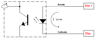
When current flows from Din+ to Din -, the output of optocoupler A is low and the Din_FPGA signal is low. When no current flows, the optocoupler output A is high and the Din_FPGA signal is high.
Installation
The OP7816 digital input module must be inserted at the back of the OP7000 simulator. The card can be installed in any of the 16 back slots, provided the front slot configuration is compatible. Refer to the page OP7000V2 Adding or Replacing Boards for more information on digital I/O card placement in the chassis - the same applies to the OP7000 chassis.
Make sure that the board is properly aligned using the guide tracks before pressing it into place.
Face Plate
The faceplate provides the DB37F connector used to connect the 16 input signals.
DB37F Connector Pins Assignment
DB37 Connector | Channel | DB37 Connector | Channel | |
1 | +IN00 | 20 | -IN00 |
|
2 | +IN01 | 21 | -IN01 | |
3 | +IN02 | 22 | -IN02 | |
4 | +IN03 | 23 | -IN03 | |
5 | +IN04 | 24 | -IN04 | |
6 | +IN05 | 25 | -IN05 | |
7 | +IN06 | 26 | -IN06 | |
8 | +IN07 | 27 | -IN07 | |
9 | +IN08 | 28 | -IN08 | |
10 | +IN09 | 29 | -IN09 | |
11 | +IN10 | 30 | -IN10 | |
12 | +IN11 | 31 | -IN11 | |
13 | +IN12 | 32 | -IN12 | |
14 | +IN13 | 33 | -IN13 | |
15 | +IN14 | 34 | -IN14 | |
16 | +IN15 | 35 | -IN15 | |
17 | 36 | |||
18 | 37 | |||
19 | ||||

Specifications
Product name | OP7816-2 |
|---|---|
Part number | 126-0389 |
Product type | OP7000 back 16 Din opto-isolated board |
Number of channels | 16 digital inputs |
Isolation | Optical isolator |
Input current | 12 Vcc @ 1.5A |
Maximum reverse voltage protection | 30 Volts |
Bandwidth | 500 kHz |
Voltage range | 0 to 5 Vcc or 5 to 50 Vcc |
Delay Low-to-High (minimum) | ≈ 40 ns |
Delay High-to-Low (maximum | ≈ 75 ns |
Dimensions | 18.8 x 16.4 cm (7.4 in x 6.46 in) |
I/O connector | DB37F |
Operating temperature | 10 to 40 ºC (50 to 104ºF) |
Storage temperature | -55 to 85ºC (-67 to 185ºF) |
Relative humidity | 10 to 90%, non condensing |
Maximum altitude | 2,000 m (6562 ft.) |
OPAL-RT TECHNOLOGIES, Inc. | 1751, rue Richardson, bureau 1060 | Montréal, Québec Canada H3K 1G6 | opal-rt.com | +1 514-935-2323
Follow OPAL-RT: LinkedIn | Facebook | YouTube | X/Twitter