Documentation Home Page ◇ HYPERSIM Home Page
Pour la documentation en FRANÇAIS, utilisez l'outil de traduction de votre navigateur Chrome, Edge ou Safari. Voir un exemple.
Examples | IEC 61850 Substation Automation System (SAS)
Location
This example model can be found in the software under the category "Protection" with the file name "IEC61850_SAS.ecf".
Description
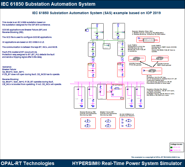
This example model shows how a substation designed based on IEC 61850 Substation Automation Systems can be represented in HYPERSIM. The single line diagram shows the hierarchy of IEC 61850 compliant substations such as bays, voltage levels. There are representations of IEDs (Intelligent Electronic Devices) which are in control of equipment for bays with their logic designed using parts from the HYPERSIM library.
The protection applications are breaker failure and reverse blocking which are explained in further sections. The communication between devices is based on GOOSE and SV. An SCD file is used to import GOOSE communication and SV is IEC 61850-9-2 SV LE which is configured in HYPERSIM I/O configuration interface. The naming of devices and IEDs tries to follow the naming conventions of IEC 61850 digital substations. Finally, by simulating the model, the protection applications are analyzed and the logic is corrected if needed.
So, the model can be an example of how to bring an IEC 61850 substation from an IEC 61850 configuration tool to HYPERSIM by using HYPERSIM devices to create single line diagram, design different protection and control applications, use the IEC 61850 communication protocols to communicate between devices, and simulate the model substation to analyze the applications.
For more information about IEC 61850 standard and its communication protocols, visit the following pages:
https://www.opal-rt.com/wp-content/uploads/2016/07/Communication-Protocol_IEC61850.pdf
https://www.opal-rt.com/iec-61850-protocol/
The substation contains the following structure:
- Two voltage levels: 230kV, 14.4kV
- Two power transformers
- Three busbars: 230 kV BUS at 230 kV voltage level, Transfer BUS XF, 14.4 kV BUS A, and 14.4 kV BUS B.
- Twelve bays:
- At 230kV:
- L1, L2 (Line)
- BP (Busbar Protection)
- TXA, TXB (Transformer Protection)
- At 14.4 kV:
- IncA, IncB (Incomer)
- BT (Tie Breaker)
- XF (Busbar XF Protection)
- A1, A2, B1, B2 (Feeder at busbars 14.4 kV BUS A and BUS B)
- At 230kV:
- Multiple IEDs at each bay are in charge of protection (PU), control (BCU) or both (PUBCU) depending on the type of IED. Merging units (MU) are located in the process level and they are in charge of digitizing current and voltage values from instrument devices and transferring them via sampled values to bay units.
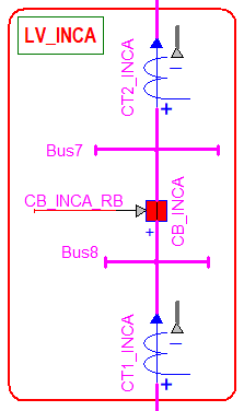
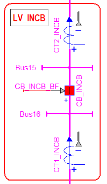
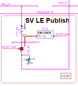
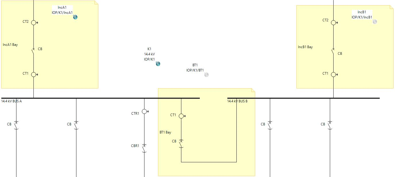
The HYPERSIM model consists of all bays mentioned above but three in particular are used for the protection application. The single line diagram in HYPERSIM is shown in the picture below for the three bays: IncA, IncB, and BT. By using HYPERSIM Parts Library, 3-phase Breakers are chosen for circuit breakers and 3-phase Current Probes are used to represent current transformers. The name of each equipment is meant to represent their respective bay so for example, the circuit breaker at the bay BT is named CB_BT. The busbars at 14.4kV are named: BUS_A, BUS_B, and TRANSFER_XF.

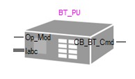
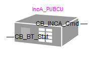
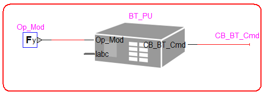
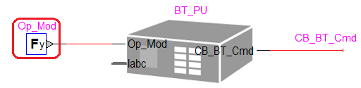
Each bay has a protection unit assigned to it which is modeled as a subcircuit in HYPERSIM and shown in the pictures below: BT_PU, IncA_PUBCU, and IncB_PUBCU. Further sections describe each IED and their roles in the protection functions.
|
|
|
|
|
|
Communication Control Blocks in the I/O Interface
HYPERSIM I/O Interface Configuration is used to create an IEC 61850 Interface. GOOSE communication from the SCD file is imported via IEC 61850 interface and IEC 61850-9-2 LE was used to configured SV streams. The current version of the IEC 61850 interface does not have the ability to import or configure MMS report control blocks.
GOOSE
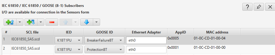
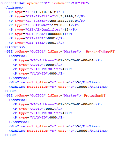
The following pictures show the I/O interface for GOOSE publisher and subscribers. The SCD file is called "IEC61850_SAS.scd"
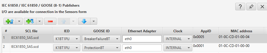
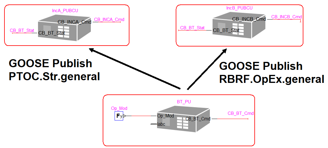
As seen from the picture, there are two GOOSE control blocks which are imported from the SCD file and both are related to the protection unit IED at the bay BT (BT_PU): BreakerFailureBT and ProtectionBT. The former is for the protection application Breaker Failure and the latter is for Reverse Blocking. The IEC 61850 data that is being published with BreakerFailureBT is RBRF.OpEx.general which is from the logical node for breaker failure protection. The IEC data that is being published with ProtectionBT is PTOC.Str.general which is from the logical node for overcurrent protection.
NOTE: For more information about logical nodes, data attributes for different functions, refer to the standard IEC 61850-7-4, IEC 61850-7-3.
NOTE: For more information about GOOSE communication, refer to the standard IEC 61850-8-1.
The publisher as shown is the protection unit at BT and subscribers are protection units at IncA and IncB. The section "Protection Applications" of this document describes what each application means and "Simulation and Results" show how they are implemented in HYPERSIM and tested in real time simulation.
The protection unit IEDs at bays IncA and IncB (InaA_PUBCU and IncB_PUBCU) are subscribers to the GOOSE messages from BT_PU.
Sampled Values
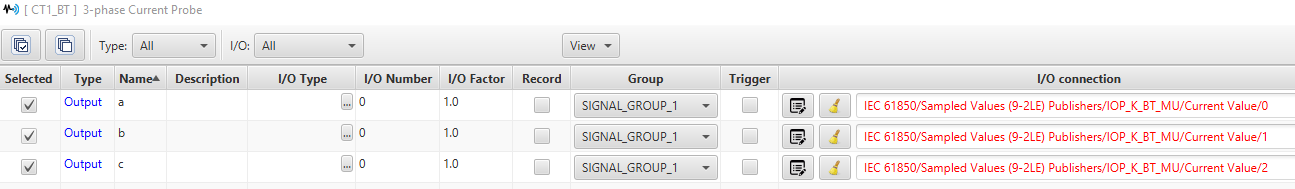
The following pictures show the IEC 61850-9-2 Sampled Values LE publisher and subscriber streams in HYPERSIM I/O interface. Like GOOSE, the streams are related to the bay BT.
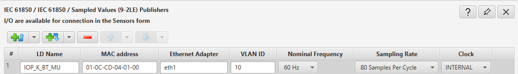
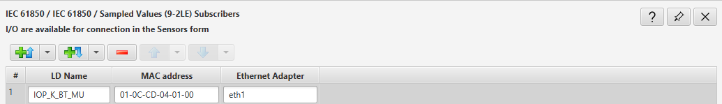
The sample value ID or LD Name as shown in the picture is called "IOP_K_BT_MU". This is to recall how there is a merging unit at BT which sends sampled values to the protection unit at the bay.
NOTE: To learn more about IEC 61850-9-2 SV LE, refer to the standard "IEC 61850-9-2" and "IEC 61850-9-2 LE Implementation Guideline".
Protection Applications
The communication section of the SCD file focus on two protection functions: Breaker Failure and Reverse Blocking between BT, IncA, and IncB. In HYPERSIM, by using breaker and fault status, GOOSE publisher and subscribers and logic inside the bay IEDs, these functions are implemented. The IEDs' output are breaker commands to IncB or IncA.
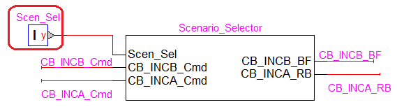
Scenario Selection
The user has the ability to choose between Breaker Failure (between CB_BT and CB_INCB) and Reverse Blocking (CB_BT and CB_INCA). The subcircuit "Scenario_Selector" makes it possible by switching between breaker command to CB_INCB and CB_INCA.
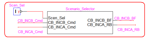
As shown in the picture, the "Scen_Sel" constant can be 1 or 2:
- 1: Breaker Failure which impacts CB_INCB operation
- 2: Reverse Blocking which affects CB_INCA operation
Breaker Failure implementation in HYPERSIM (Scen_Sel = 1)
According to the SCD file and IEC 61850 engineering, the breaker failure GOOSE control block "BreakerFailureBT" publishes the signal "RBRF.OpEx.ST.general" which is the external operating signal from the breaker failure logical node from the protection unit at BT to units from IncA and IncB to inform them of the circuit breaker failure at BT.
NOTE: Refer to IEC 61850-7-4 and IEC 61850-7-2 for more information about the IEC 61850 data model.
In HYPERSIM, for the sake of simplicity, the breaker failure implementation is done between the bays BT and IncB. When Scen_Sel = 1, if CB_BT fails to open within time when a fault occurs, CB_INCB should operate. If CB_BT opens in time, CB_INCB has to stay closed.
Reverse Blocking Implementation in HYPERSIM (Scen_Sel = 2)
According to the SCD file and IEC 61850 engineering, the reverse blocking GOOSE control block "ProtectionBT" publishes the signal "PTOC.Str.ST.general" from the protection unit at the bay BT to protection units from IncA and IncB to block their protection operation.
NOTE: Refer to IEC 61850-7-4 and IEC 61850-7-2 for more information about the IEC 61850 data model.
In HYPERSIM, as with Breaker Failure, to make the application easier to analyze, the reverse blocking implementation is done between the bays BT and IncA. So, when Scen_Sel = 2, if CB_BT opens within a time limit after fault occurs and tripping signal by the overcurrent relay is sent, CB_INCA is blocked from opening and stays closed. However, if CB_BT fails to open after a delay, CB_INCA will operate and open.
Simulation and Results
Workflow
There are two main protection function scenarios in this model and the workflow is the following:
- The fault Flt1 at the bay BT operates at 0.2 seconds and lasts until 0.4 seconds.
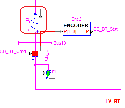
- CT1_BT publishes IEC 61850-9-2 SV LE streams to the BT_PU IED.
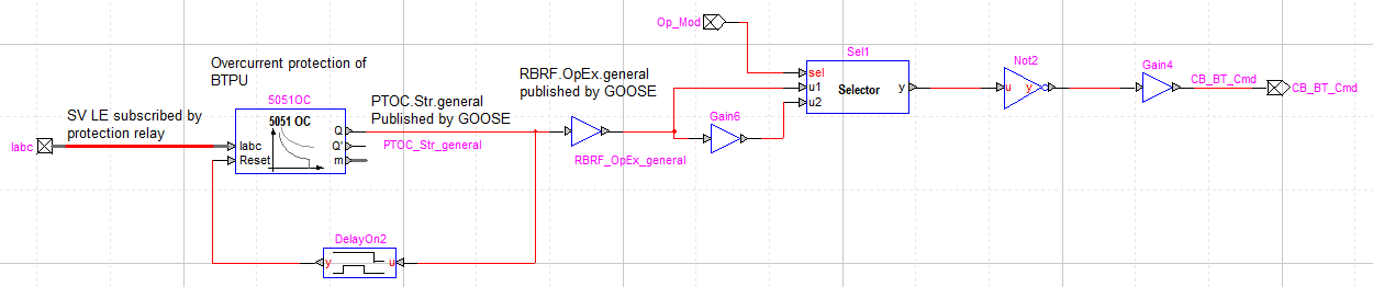
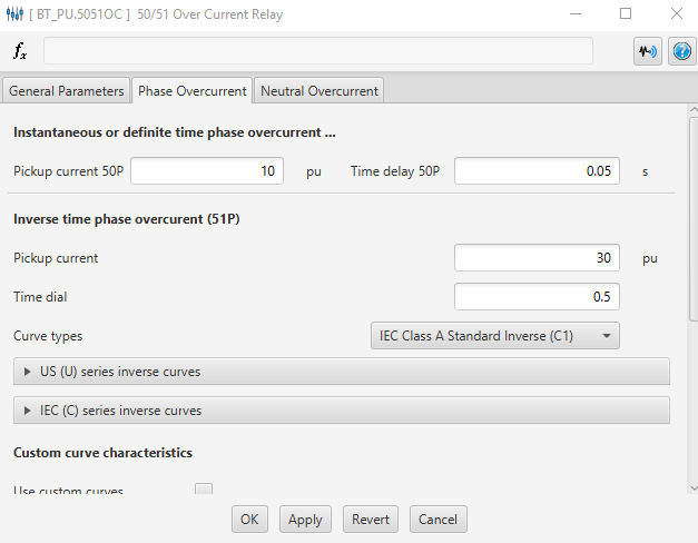
- The IED BT_PU is assigned to the bay and contains an overcurrent relay which subscribes to the SV streams from CT1_BT. It then detects the fault through instantaneous overcurrent element (50P) and sends a tripping signal which means the output (Q) becomes 1 after the relay time delay which is 0.05 seconds. Based on the CB_BT operation mode (Op_Mod), CB_BT either opens at 0.25 seconds or it fails to open. The following pictures show the BT_PU IED and elements inside the subcircuit and the relay settings. Notice how the CB_BT_Cmd is the output of the subcircuit and is linked to the input of CB_BT.
- The GOOSE message for breaker failure application is being published and transmits RBRF.OpEx.general. The other GOOSE message for reverse blocking application transmits PTOC.Str.general.
- The status of the breaker CB_BT is transmitted to the IEDs at IncA and IncB bays.
- The IEDs, IncA_PUBCU and IncB_PUBCU receive the GOOSE message from BT_PU along with the CB_BT status. Depending on their internal logic, they send a command to their respective breakers to either open or stay closed.
- IncA_PUBCU is assigned to the bay IncA and is connected to the reverse blocking protection application.
Load Flow
The simulation should be run in steady state so make sure the network is initialized by the load flow.
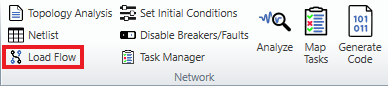
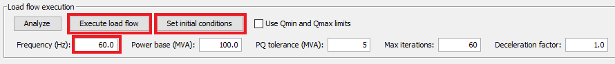
Open Network → Load Flow, make sure the frequency is at 60 Hz and then press "Execute load flow".
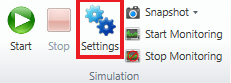
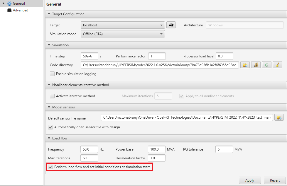
You can also enable performing load flow when simulation starts in the "Simulation Settings".
Two scenarios exist in this model as discussed in the previous section which can be chosen by Scen_Sel:
- 1: Breaker Failure
- 2: Reverse Blocking
Scenario 1: Breaker Failure (Scen_Sel = 1, Op_Mod = 2)
Flt1 is activated at 0.2 seconds. The overcurrent relay 5051OC from BT_PU IED detects the overcurrent and sends a tripping signal at 0.25 seconds. CB_BT fails to open at that time and so CB_INCB opens at 0.25 seconds.
- Set Scen_Sel = 1
- Set Op_Mod = 2 so CB_BT fails to open.
- Run the simulation on a target and again, make sure load flow is executed.
The relay BT_PU.5051OC will detect the overcurrent after 0.05 seconds delay and Q =1. The signal "RBRF.OpEx.general" is published via the GOOSE control block "BreakerFailureBT" to IncB_PUBCU. The IED also receives the status for CB_BT (CB_BT_Stat).
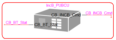
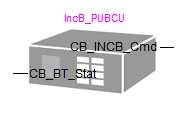
The following picture shows the logic inside IncB_PUBCU.
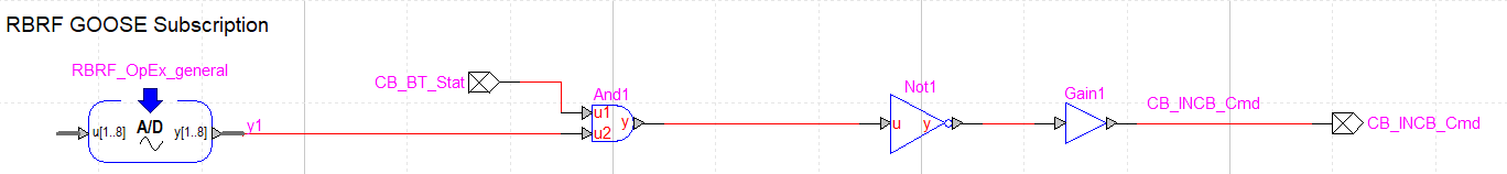
The RBRF_OpEx_general block subscribes to the the signal from the overcurrent relay (RBRF.OpEx.general). It is compared with the status of CB_BT (CB_BT_Stat). If CB_BT is closed while relay has operated, it means CB_BT has failed to open and so the command is sent to CB_INCB to open via CB_INCB_Cmd.
- Open the ScopView template "IEC61850_SAS.svt".
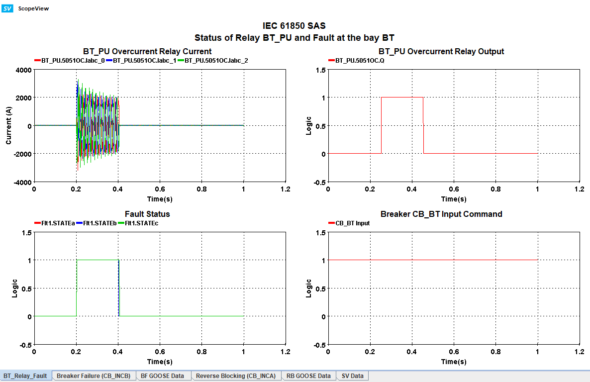
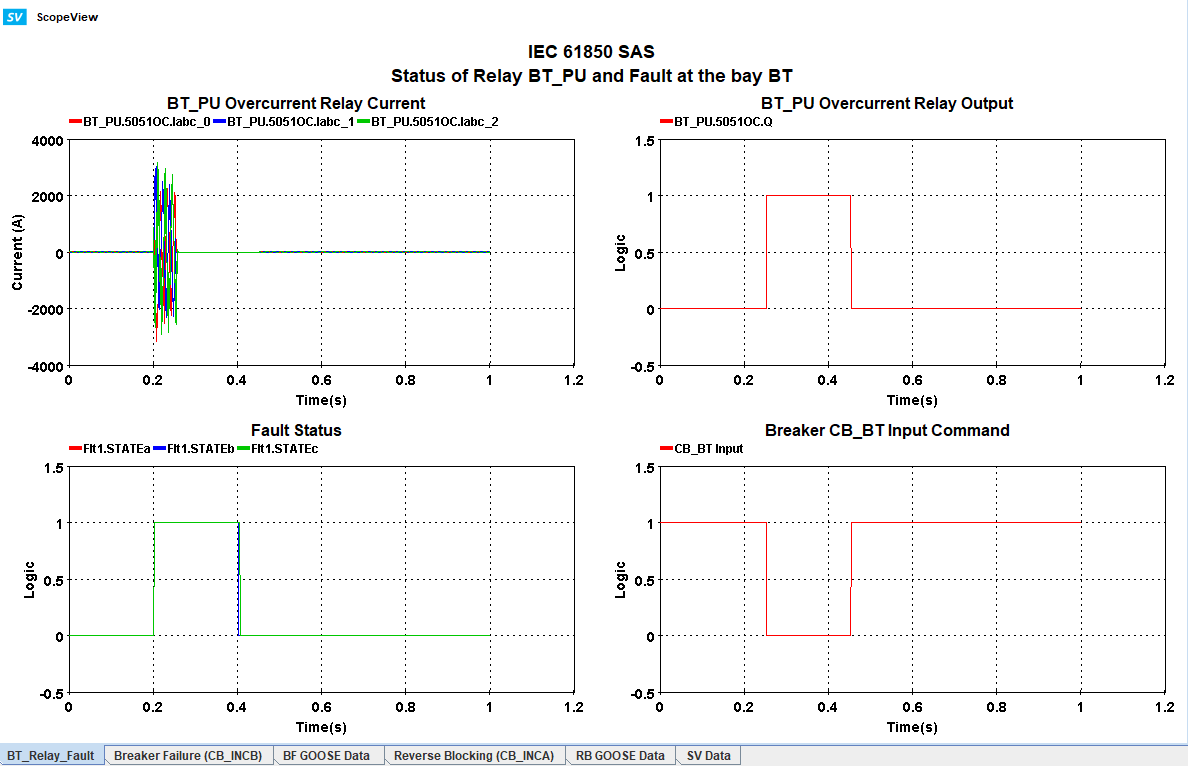
The tab "BT_Relay_Fault" shows the BT_PU overcurrent relay input current which are SV subscribes to the CT1_PU current transformer, the fault status, the relay output (Q), and the CB_BT input command from BT_PU IED.
Notice how the CB_BT input command does not drop to zero to make sure CB_BT opens during fault. This means CB_BT has failed to open even though there is a fault and is detected by the BT_PU overcurrent relay (Q).
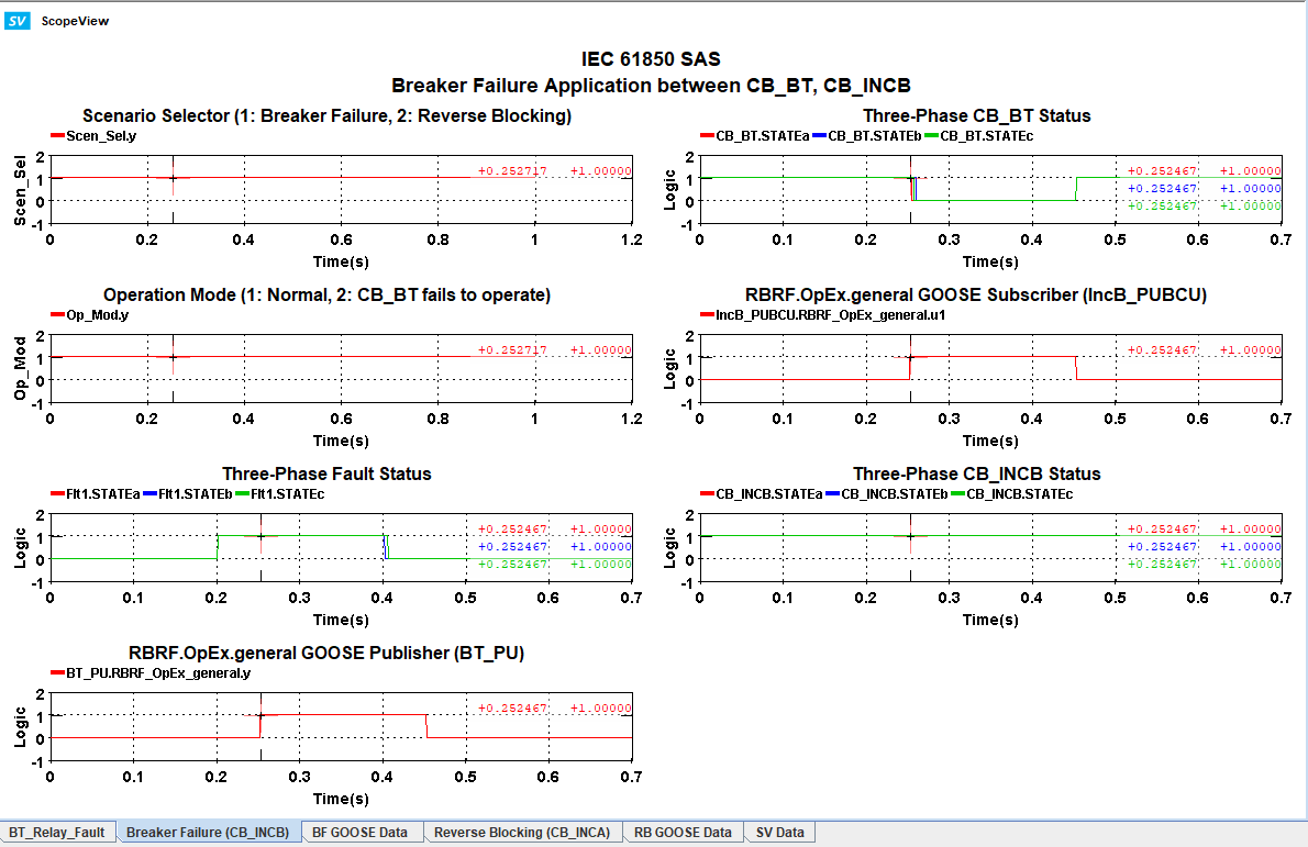
The following figure is from the tab "Breaker Failure (CB_INCB)" which shows the status of breakers CB_BT and CB_INCB. It is clear how CB_BT failed to open at 0.25 seconds but CB_INCB operates at that time and opens its contacts for all phases. This isolates the fault and protects the busbar.
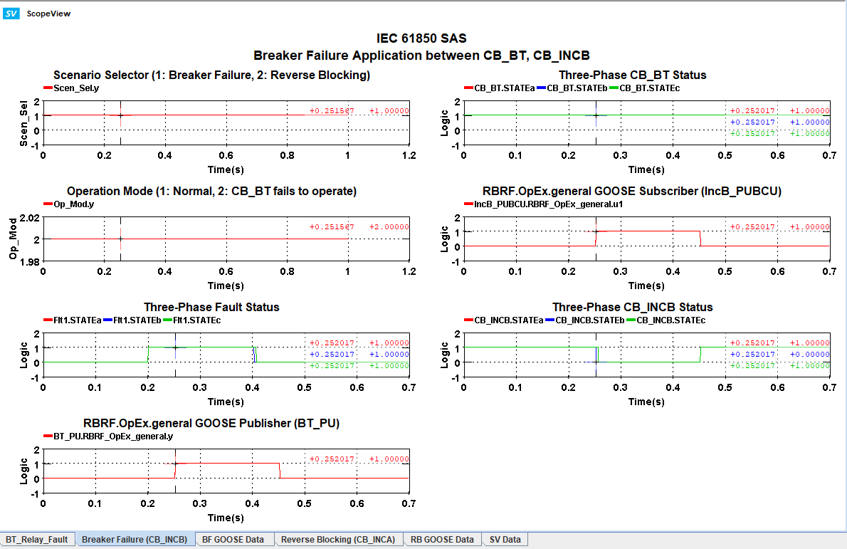
- Set Op_Mod = 1 and view the same tab in ScopeView.
In this case, it can be seen from the figure that CB_BT opens at 0.25 seconds, so CB_INCB stays closed as intended.
Scenario 2: Reverse Blocking (Scen_Sel = 2, Op_Mod = 1)
Flt1 is activated at 0.2 seconds. The overcurrent relay 5051OC from BT_PU IED detects the overcurrent and sends a tripping signal at 0.25 seconds. If CB_BT opens at that time, CB_INCA is blocked from operating. However, if CB_BT fails to open at 0.25 seconds plus an additional 0.05 seconds, then CB_INCA has to open.
- Set Scen_Sel = 2

- Set Op_Mod = 1

- Run the simulation and make sure load flow is executed.
The relay BT_PU.5051OC will detect the overcurrent after 0.05 seconds delay and Q =1. The signal "PTOC.Str.general" is published via the GOOSE control block "ProtectionBT" to IncA_PUBCU. The IED also receives the status for CB_BT (CB_BT_Stat).
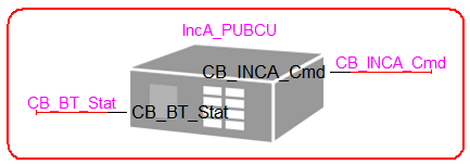
The following picture shows the logic inside IncA_PUBCU IED:
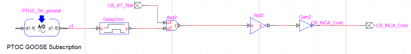
The PTOC_Str_general block subscribes to the signal from the overcurrent relay (PTOC.Str.general) and is delayed an additional 0.05 seconds so there is more time for CB_BT to operate. It is compared with CB_BT_Stat and if CB_BT is open, the blocking signal is sent to CB_INCA to ensure it stays closed.
- Open ScopeView and the template "IEC61850_SAS.svt".
The first tab shows the BT_PU overcurrent relay input current, its output, fault status and the CB_BT input command. Notice how it has turned to zero meaning CB_BT has to open at 0.25 seconds.
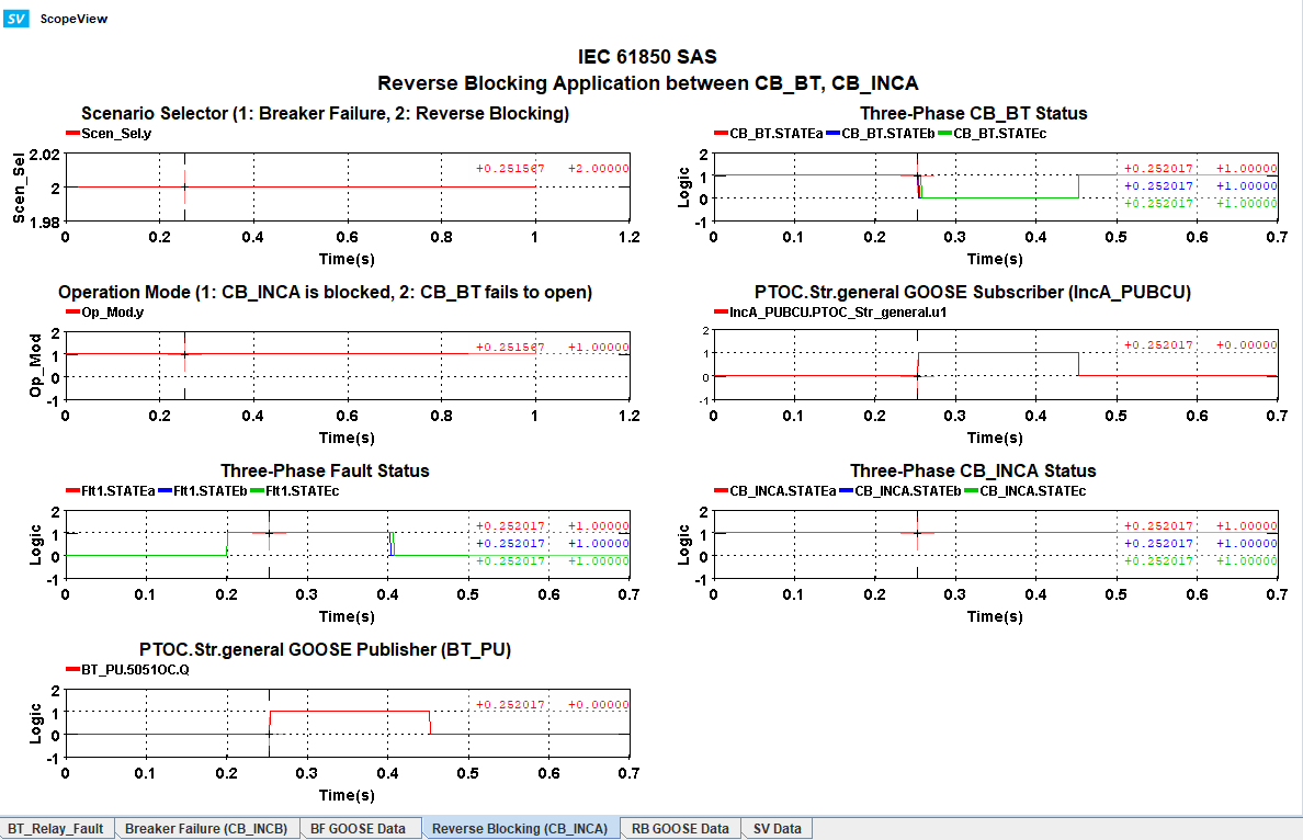
The tab "Reverse Blocking (CB_INCA)" shows the operation of CB_BT and CB_INCA. As expected, CB_BT is open at 0.25 seconds and CB_INCA is blocked and has stayed closed.
- Change Op_Mod = 2 and view the same tab in ScopeView template.
It is clear how CB_BT has failed to open and CB_INCA operates at 0.3 seconds which is 0.25 + 0.05 seconds as intended.
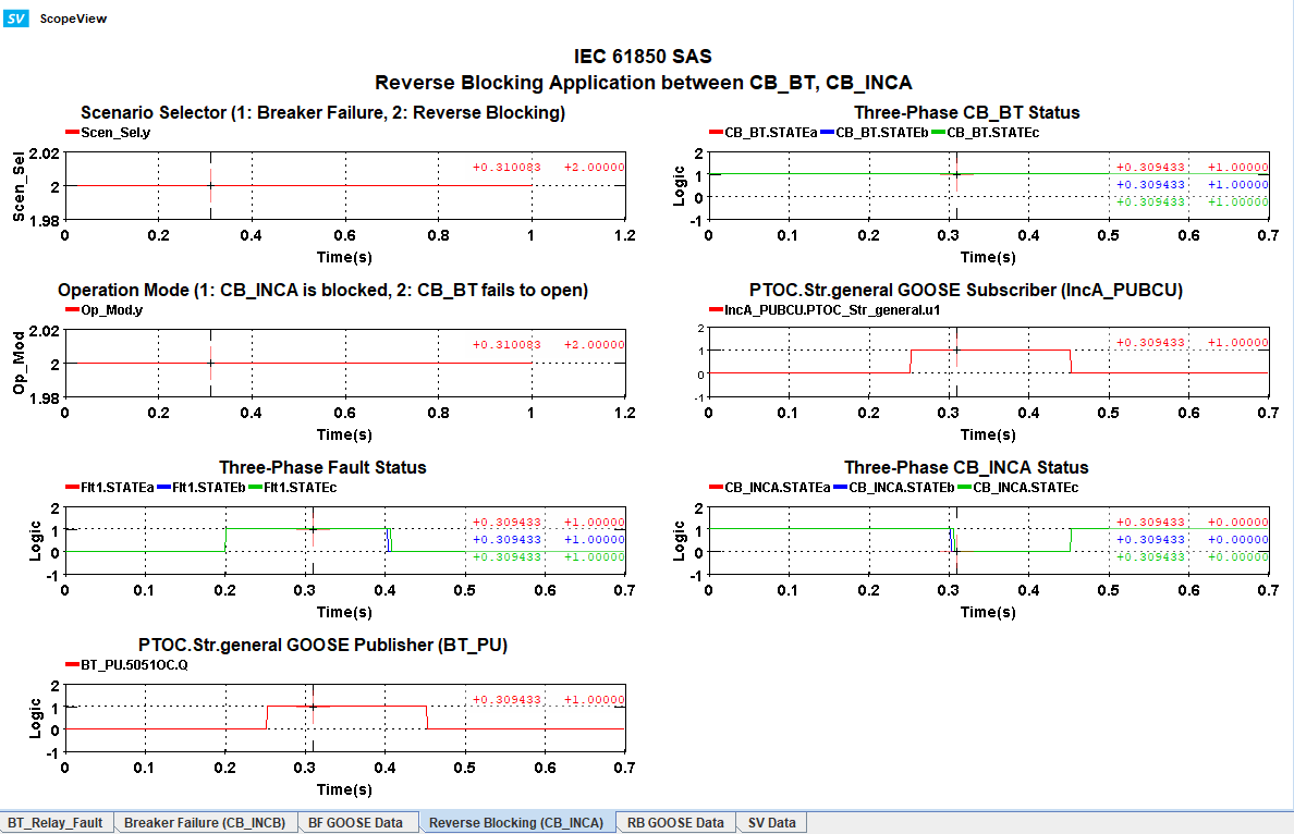
So, CB_INCA is blocked from operating as long as CB_BT is performing as expected.
GOOSE and SV Monitoring
GOOSE Status
The tabs "BF GOOSE Data" and "RB GOOSE Data" shows the monitoring data for the GOOSE control blocks "BreakerFailureBT" and "ProtectionBT" respectively for breaker failure and reverse blocking applications.
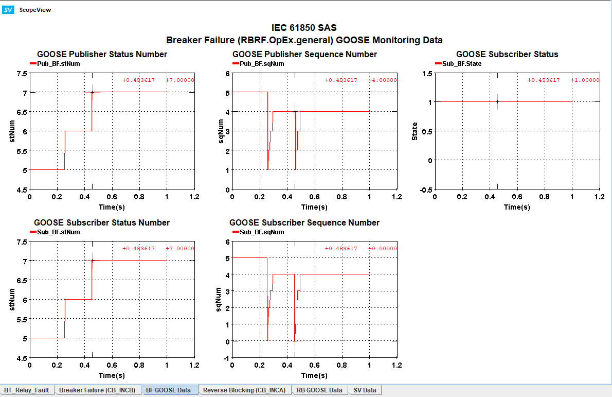
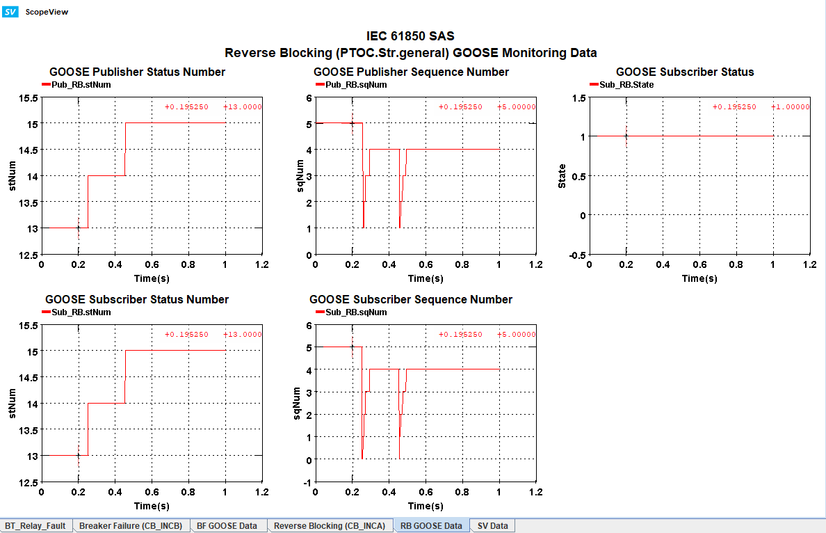
The status data attribute which being monitored to determine the health of the connection between the publisher and subscriber.
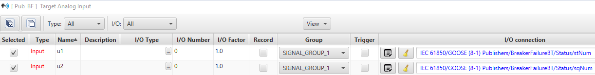
- stNum (Status Number) for publisher and subscriber: This data attribute increments whenever the status of the GOOSE message changes. So, in the case of the protection functions in this model, whenever the output of the relay BT_PU.5051OC (Q) changes its status, this number increments by 1. If a connection between publisher and subscriber is maintained, stNum for both publisher and subscriber should be the same value.
- sqNum (Sequence Number) for publisher and subscriber: This data attribute increments whenever the GOOSE message is retransmitted which differs for each GOOSE control block. It rests to 0 or 1 (depending on the GOOSE control block parameters). So, in this model, whenever the fault is reinitialized and the relay output changes its status, sqNum resets to 0. sqNum should be the same for both publisher and subscriber as long as their connection is established and maintained.
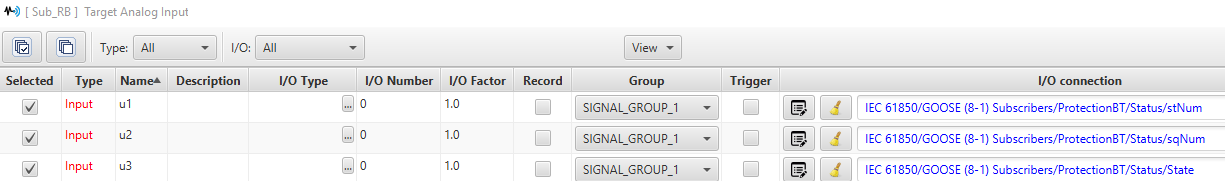
- State for subscriber: This data attribute has the value of 1 when the connection between publisher and subscriber is established. If they lose connection, the value drops to 0. If subscriber falls behind the publisher and so is not un synchronization with it anymore, the value changes to -5.
As shown in the picture, the values for stNum, sqNum for both publisher and subscriber are the same and also State = 1 so a connection has been successfully established between GOOSE publisher and subscriber.
SV Data
The following figure shows the status for SV from the tab "SV Data" from the ScopeView template.
The data here contains the SV publisher and subscriber current waveforms. The SV Publisher streams are from the output sensors of CT1_BT and the SV Subscribers are the input sensors of the 5051OC relay from BT_PU. Each stream is being sampled and the higher the current, the smoother the subscriber waveform will be.
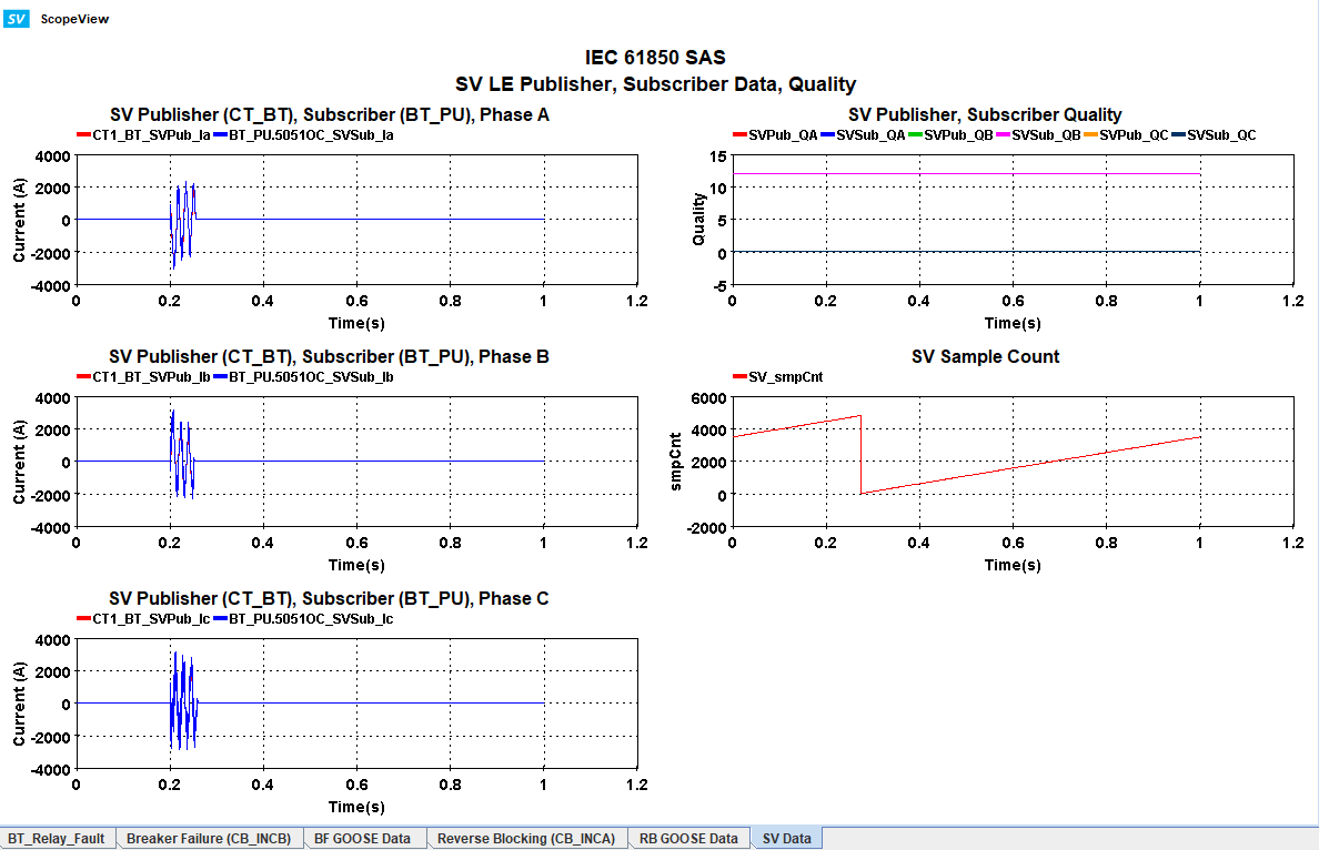
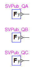
The SV Publisher and Subscriber Quality waveforms are from the constant blocks SVPub_Q which are publishing the quality value for current SV streams. If the subscriber values are the same as the publisher, as shown in the figure, it means the connection between the publisher and subscriber is valid.
SV Sample Count shows the smpCnt value of the SV stream. This data attribute is typically used for synchronization validation. According to the standard, an IEC 61850-9-2 LE compliant merging unit can publish analog data at a fixed rate which is 80 samples per power cycles. The number of samples per second is 4800 for a 60 Hz system (like this model) and 4000 for a 50 Hz system. The figure shows how smpCnt reaches 4800 in one second.
Additional Information
Substation Origins
This section shows the design reference for this model.
The model is based on the substation designed by the IEC 61850 User Group under the UCA International User Group (UCAIUG) during the IOP conferences of 2017 and 2019 [1]. The single line diagram of the model can be seen in the figure below.
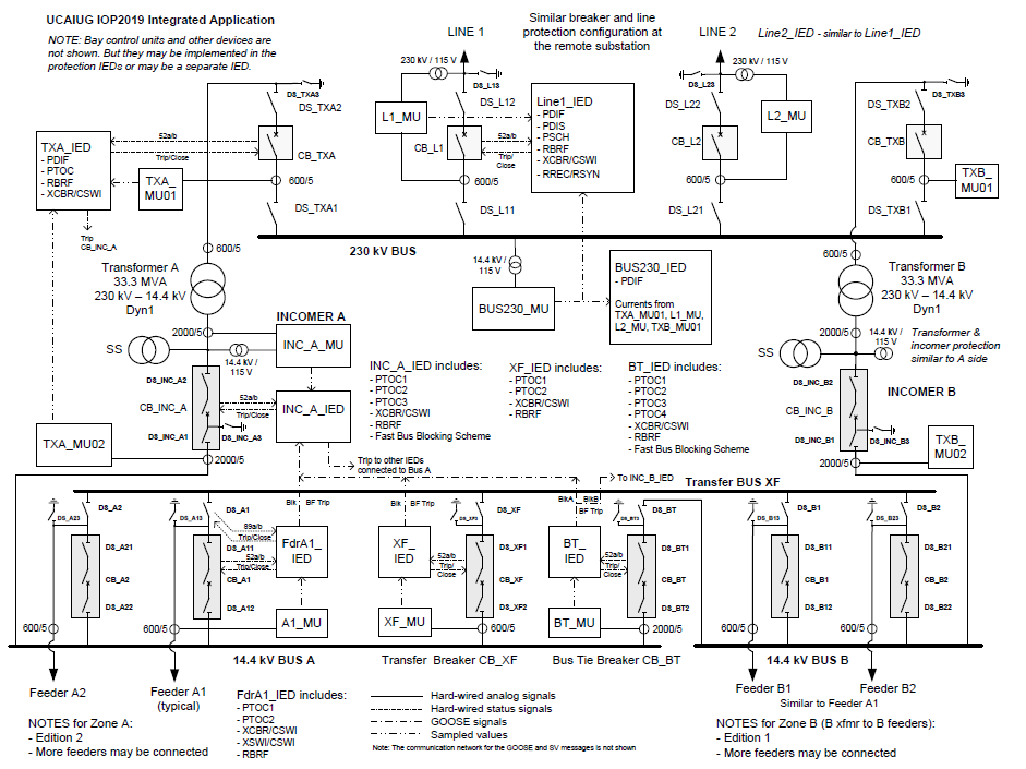
Helinks STS, a vendor-independent system configuration tool was used to design the SAS based on the IOP substation [2]. The design focuses on three bays at the 14.4 kV voltage level: IncA, IncB, BT. The result of the SAS design in Helinks STS is an SCD file which contains all information from the substation including communication.
The picture below shows the design of the three bays in Helinks STS.
The following picture shows a part of the SCD file, specifically the GOOSE communication section.
GOOSE and SV Sensor Mapping
This segment shows the mapping sensors of HYPERSIM library parts to IEC 61850 data from GOOSE and sampled values. The information is given for each bay.
BT
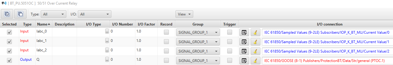
CT1_BT
BT_PU IED
5051OC Relay for SV Current Input and PTOC.Str.general publishing
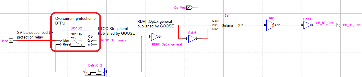
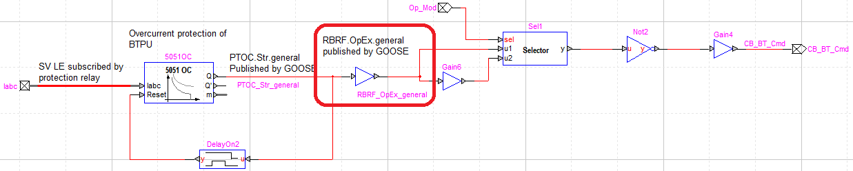
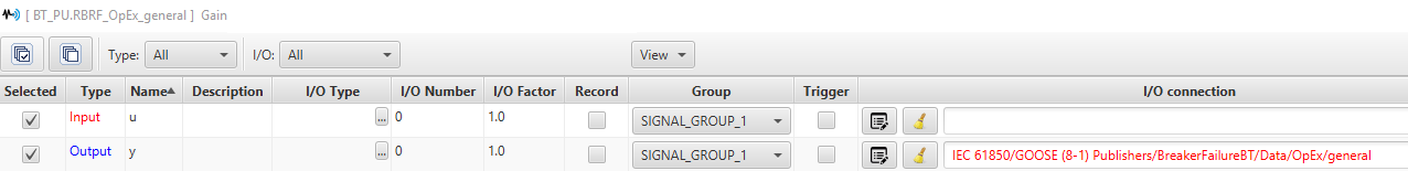
Gain "RBRF_OpEx_general" for RBRF.OpEx.general publishing
IncB
IncB_PUBCU
Target Analog Input "RBRF_OpEx_general" for RBRF.OpEx.general subscription

IncA
InA_PUBCU
Target Analog Input "PTOC_Str_general" for PTOC.Str.general subscription

GOOSE and SV Monitoring Data
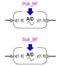
GOOSE monitoring data for Breaker Failure Application
Target Analog Input Pub_BF, Sub_BF for stNum, sqNum, State
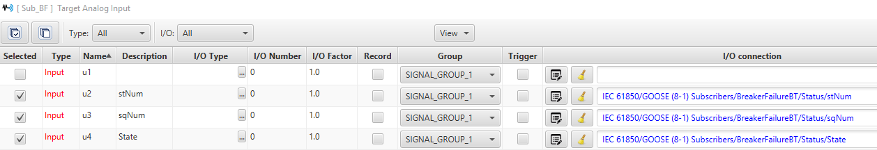
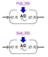
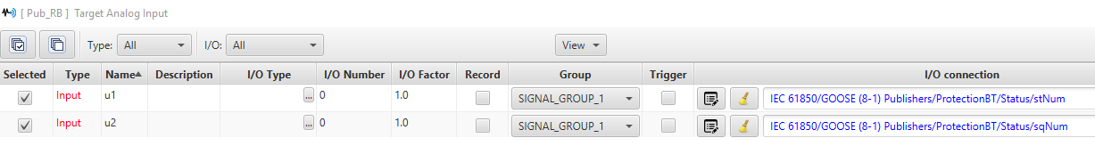
GOOSE monitoring data for Reverse Blocking Application
Target Analog Input Pub_RB, Sub_RB for stNum, sqNum, State
SV IEC 61850-9-2 LE Data
Constants SVPub_QA, SVPub_QB, SVPb_QC for Current Quality publishing


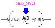
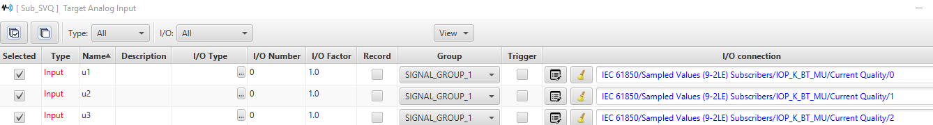
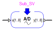
Target Analog Input "Sub_SVQ" for Current Quality subscription
Target Analog Input "Sub_SV" for smpCnt

References
OPAL-RT TECHNOLOGIES, Inc. | 1751, rue Richardson, bureau 1060 | Montréal, Québec Canada H3K 1G6 | opal-rt.com | +1 514-935-2323