Documentation Home Page ◇ HYPERSIM Home Page
Pour la documentation en FRANÇAIS, utilisez l'outil de traduction de votre navigateur Chrome, Edge ou Safari. Voir un exemple.
Examples | Transformer Differential Protection
- Sylvain Ménard
Location
This example model can be found in the software under the category "Protection" with the file name "Transformer_Differential_87T.ecf".
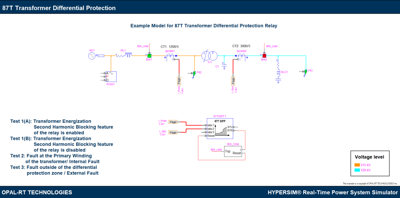
Description
This example model is to demonstrate the functionalities of the transformer differential relay [1]. A 315 kV / 120 kV YD11 connection transformer is connected to a simple transmission system. A 300 MW, 50 MVAR constant impedance load is connected to the secondary side of the transformer. Current probes CT1 and CT2 are installed to represent the current transformers and are selected to have a ratio of 1200/5 and 3000/5 respectively.
The CT measurements are connected to the differential protection relay.
Simulation and Results
During transformer energization, a high magnetizing current inrush occurs on the energized windings. The inrush current is not transferred to the unloaded windings (e.g. secondary), which leads to differential currents. The inrush current may typically contain 2nd, 4th and 5th harmonics and transformer differential protections can detect this harmonic signature and mitigate false differential tripping. In this example, the 2nd harmonic blocking function is activated to demonstrate the harmonic blocking functionality.
Case 1: Transformer Energization
Open the control panel of Brk1, in the ‘Timing’ tab, enable ‘General operation’ and configure the ‘Steady-state condition’ to be open for all three phases. Enable T1, T2 and T3 and configure as follows:
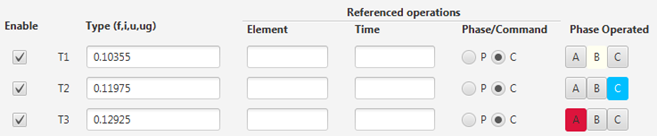
This allows Brk1 to close and to energize the transformer (phase A at 0.12925 s, phase B closes at 0.10335 s and phase C at 0.11975 s).
Now, start the simulation and launch ScopeView, open the template: ‘Transformer_Differential_87T.xml’.
Check both ‘Sync’ and ‘Trig’ and start the data acquisition. The figure below shows the transformer primary and secondary winding currents as well as the flux.
![]()
The CT measurements which are sent to the differential relay as well as the 87R trip signal from the relay are shown below.
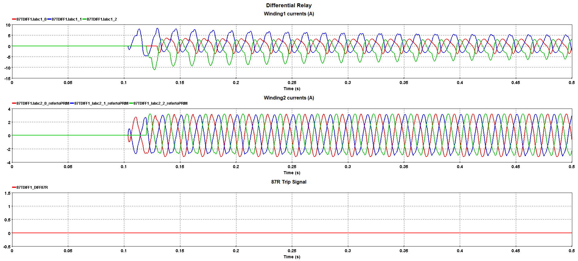
It can be seen in the figure below that during energization, the differential currents are higher than 0.2 pu. However, the 2nd harmonic component in differential currents is higher than 20 % of the fundamental component and thus blocks the relay from tripping on energization.
.png?version=1&modificationDate=1678998871380&cacheVersion=1&api=v2&width=1000&height=452)
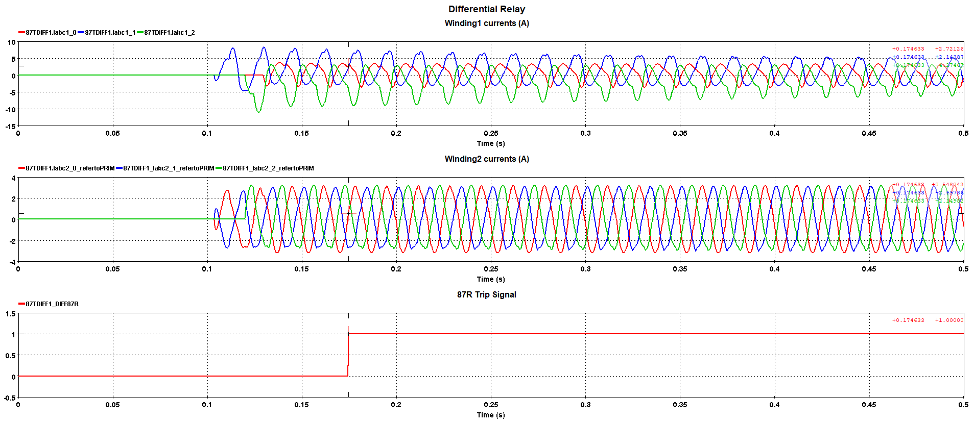
If harmonic blocking is disabled, the trip signal is asserted at t = 0.17463 s as shown in the figure below, which is 45.3 ms after the last phase is closed. This corresponds to the 40 ms time delay settings in the relay.
Case 2: Fault at the Primary Winding of the Transformer
Open the control panel of Brk1, in ‘General’ tab, change the ‘Control type’ from ‘Internal’ to ‘External (input pins)’. In ‘Timing’ tab, disable ‘General operation’ and configure the ‘Steady-state condition’ as closed for all three phases. Apply the same configuration to Brk2. In this way, the trip signal from the differential relay controls the switching operation of Brk1 and Brk2.
Open the control panel of Flt2, which is connected at the primary winding of the transformer. Enable ‘General operation’ in the ‘Timing’ tab. A single-line-to-ground fault (A-G) will be applied to the primary winding at t = 0.1 s.
Disable the Harmonic blocking function in the 87T model.
Make a data acquisition in ScopeView with ‘Sync’ and ‘Trig’ checked. The primary winding currents, the secondary winding currents and the flux are shown in the figure below.
![]()
The two CT measurements and the relay trip signal are shown below. The relay sends the trip signal at t = 0.1509 s to open the breaker, which is 50.9 ms after the fault occurs which is in accordance with the set Trip delay of 40 ms.
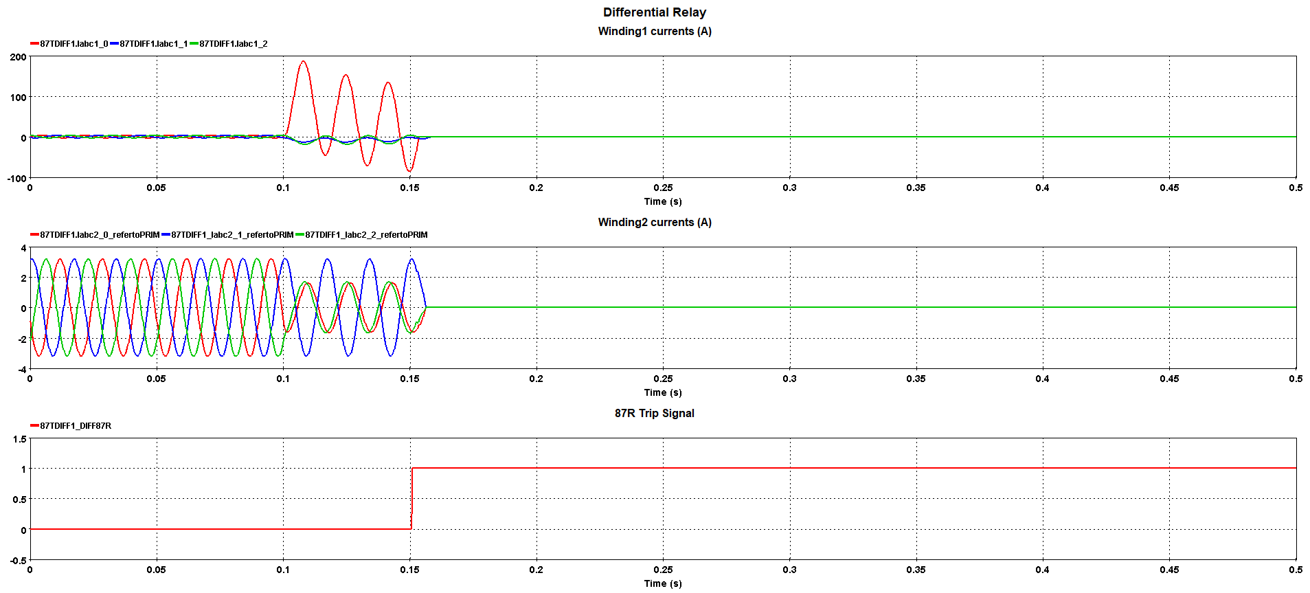
The figure below shows the calculated differential currents.
.png?version=1&modificationDate=1678998871101&cacheVersion=1&api=v2&width=1000&height=452)
Case 3: Fault Outside of the Differential Protection Zone
Open the control panel of Flt2, disable ‘General operation’ in the ‘Timing’ tab. Open the control panel of Flt1 which is next to the load. Enable ‘General operation’ in the ‘Timing’ tab. In this case, a single line-to-ground fault (B-G) is applied near the load at t = 0.1 s.
The primary winding currents, the secondary winding currents and the flux are shown in the figure below.
![]()
As shown below, the differential relay does not trip as the fault is outside the differential protection zone.
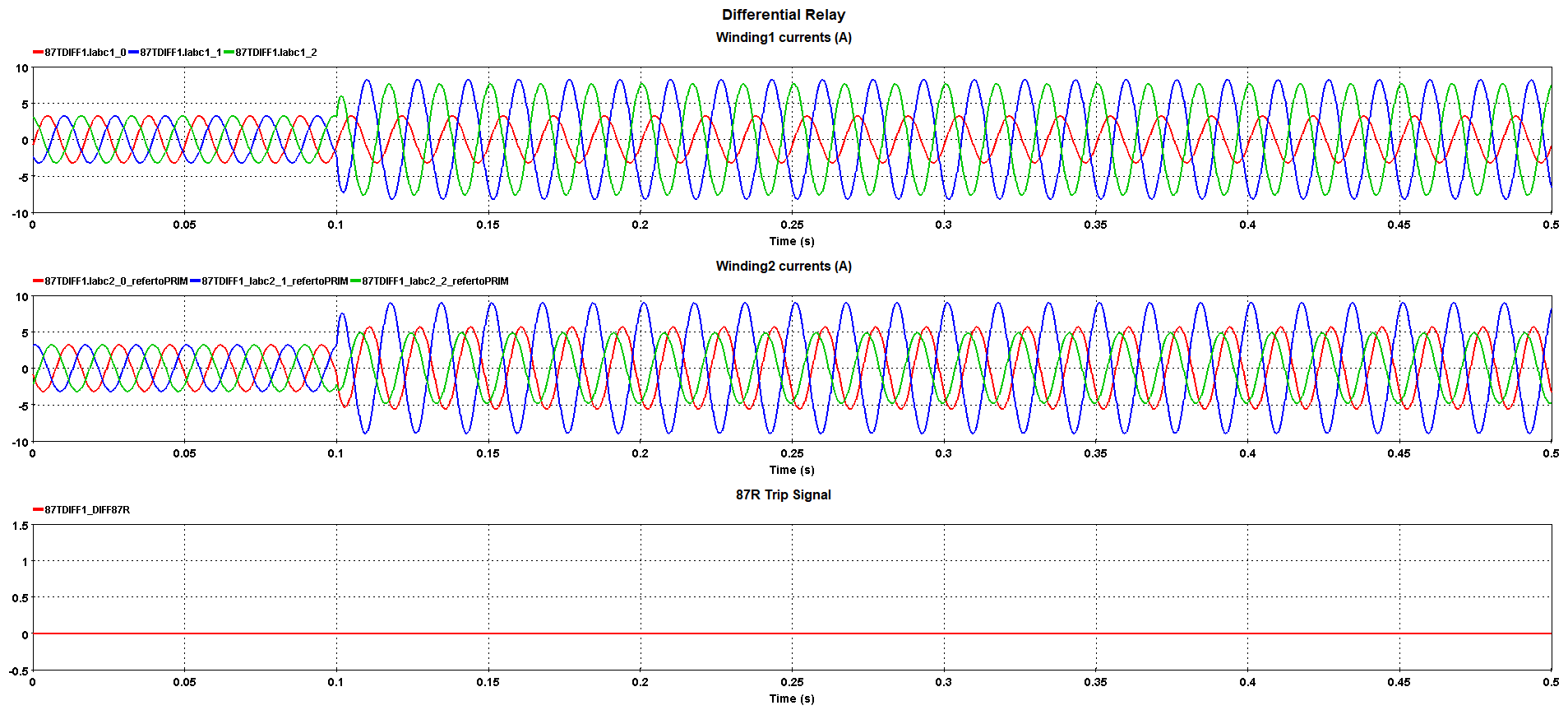
It can be seen in the figure below that there is no differential current between the primary and the secondary side of the transformer.
.png?version=1&modificationDate=1678998870791&cacheVersion=1&api=v2&width=1000&height=452)
References
[1] EMTP-RV example model: Protection – Differential – Transformer_Energization
OPAL-RT TECHNOLOGIES, Inc. | 1751, rue Richardson, bureau 1060 | Montréal, Québec Canada H3K 1G6 | opal-rt.com | +1 514-935-2323
Follow OPAL-RT: LinkedIn | Facebook | YouTube | X/Twitter