Documentation Home Page ◇ Hardware Home Page
Pour la documentation en FRANÇAIS, utilisez l'outil de traduction de votre navigateur Chrome, Edge ou Safari. Voir un exemple.
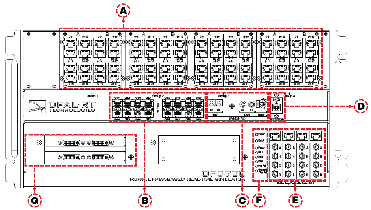
OP5700 Front Connectors
A. RJ45 connector panels provide connections to monitor signals from mezzanine I/O boards. Each connector is linked to front and back mezzanines on the carrier board. Analog mezzanines (channels 0-15) use only the first column of connectors.
Digital mezzanines use both columns (channels 0-15 in the first column and channels 16-31 on the second column of connectors). See the OP5700 General Pin Assignments for more detailed information.
B. 16 SFP (small form-factor pluggable) ports controlled from the FPGA, for high-speed communication with other simulators, FPGAs or with third-party devices. Each socket controls one communication link.
SFP transceivers and optical fiber cables must be selected according to the type and speed of the communication protocol implemented in the FPGA.
Note: MUSE link requires specific SFP transceivers and optical fiber cable:
- SFP transceiver: Avago AFBR-57R5APZ
- Cable: LC-LC multimode 850nm optical fiber
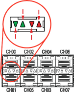
The LEDs (light pipes) associated to the selected channel will light to indicate the channel is selected. LEDs are arrow-shaped to indicate the channels to which they are associated. The LED upward arrow points to the top channel, the downward arrow points to the bottom channel (see below):
LED | Color | Description | CH00 CH01 |
|---|---|---|---|
or | Green | ON = SFP transceiver is inserted OFF = no SFP transceiver present BLINK = channel active | |
or | Red | OFF = no fault ON = transmission fault BLINK = reception loss |
C. Synchronization connectors (fiber optic and audio) and a series of four LEDs on the front panel display the device status
LED | Power On | After Load & During Execution | After Reset |
|---|---|---|---|
Tx | OFF | GREEN** | OFF |
Rx | OFF | GREEN** | OFF |
M/S | Default* | ORANGE = Slave | GREEN |
PWR | GREEN | GREEN | GREEN |
Note:
*The color of the M/S LED at power up depends on the default FPGA configuration: when the FPGA board is programmed in slave synchronization mode, the LED is orange; when it is programmed in master mode, the LED is green.
**Tx and Rx provide synchronization information. When transmitting the synchronization signal, the Tx LED is green. When receiving the synchronization signal, the Rx LED is green.
E. Monitoring RJ45 connectors with mini-BNC terminals for monitoring: RJ45 cables connect from a channel on an RJ45 panel (A) to one of four RJ45 monitoring connectors (E). Mini-BNC connectors allow for quick cable connections to monitoring devices (such as an oscilloscope). See OP5700 Installation and Configuration for details.
F. Target computer monitoring interface. Two pushbuttons include POWER in top position to start the Target computer and RESET in the bottom position to reset the Target computer. There are 6 LED indicators:
LED | NAME | Description |
Green | Power | On indicates that the unit is powered up. |
Green | HDD | On indicates that the hard disk drive is operating. |
Green | NIC1 | On indicates that network port 1 is in use. |
Green | NIC2 | On indicates that network port 2 is in use. |
Red | Power Fail | On indicates a power fault. |
Red | Overheat/Fan Fail | On indicates either that unit has overheated or a fan fault. |
G. PCI or PCIe connector slots. By default, these spaces are covered by blank plates if there are no optional PCI or PCIe boards installed in the chassis. If there are boards installed, the spaces give access to the card connectors.
OPAL-RT TECHNOLOGIES, Inc. | 1751, rue Richardson, bureau 1060 | Montréal, Québec Canada H3K 1G6 | opal-rt.com | +1 514-935-2323
Follow OPAL-RT: LinkedIn | Facebook | YouTube | X/Twitter


