Documentation Home Page ◇ Hardware Home Page
Pour la documentation en FRANÇAIS, utilisez l'outil de traduction de votre navigateur Chrome, Edge ou Safari. Voir un exemple.
OP8216 DB37 to 16 Fiber Optic interface
- Sylvain Ménard
![]()
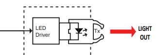
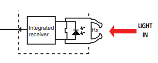
The OP8216 is an 1U fiber optic channel interface output (TX) or input (RX) depending on selected configuration.
The board holds optical transceivers and converts logic signals into fiber optic signals (transmit channels), and fiber optic signals into digital logic signals (receive channels). Hence it ensures optical digital input and output isolation between the OPAL-RT simulator and the unit under test.
The transceivers are compatible with plastic optical fiber cables (650nm wavelength). Their frequency range is DC to 25 MHz, corresponding to a 50 Mbps baud rate, for distances up to 50 meters. The absolute minimum for transmission (Tx) high and low pulse width is 20ns. This frequency range means the board can be used as a standard digital I/O card with isolation (DC mode), or for low-speed communication protocols.
Possible configuration are :
| Product Name | Configuration | Description |
|---|---|---|
| OP8216-16-1 | 16 ch. Tx | DB37 to 16 Fiber Optic Output Interface Panel |
| OP8216-32-1 | 32 ch. Tx | 2xDB37 to 2x16 Fiber Optic Output Interface Panel |
| OP8216-16-2 | 16 ch. Rx | DB37 to 16 Fiber Optic Input Interface Panel |
| OP8216-32-2 | 32 ch. Rx | 2xDB37 to 2x16 Fiber Optic Input Interface Panel |
| OP8216-32-3 | 16 ch. Tx/ 16 ch. Rx | 2xDB37 to 16 Fiber Optic Input and 16 Fiber Optic Output Interface Panel |
Specifications
| Product Name | OP8216 |
|---|---|
| Product type | 8TX_8RX_DC_to_50_MBd_Fiber_Optic_link_650nm |
| Receiver Type | AFBR-2624Z PIN diode |
| Transmitter Type | AFBR-1624Z 650nm wavelength |
| Connector Type | Avago’s Versatile Link family |
| Maximum Tx/Rx Frequency | 50Mbps when connected to I/O Mezzanine Board OP5351, OP5352 and OP5367 10Mbps when connected to I/O Mezzanine Board OP5353 and OP5360 2Mbps when connected to I/O Mezzanine Board OP5369 |
| Minimum Tx Pulse Width | 20 ns |
| Transmitter Input Electrical Signal | TTL-level compatible +3.3V or +5V. |
| Receiver Output Electrical Signal | TTL-level compatible +5V. |
| External power supply | 12VDC ( ±20% ) 10W is required (J1 connector on PCB) |
| Rack Unit | 1U |
| Dimensions | 18.8 x 16.4 x 4.4 cm (17.43 in x 6.46 in x 1.75 in) |
| Operating Temperature | 10 to 40 ºC (50 to 104ºF) |
| Storage Temperature | -55 to 85ºC (-67 to 185ºF) |
| Relative Humidity | 10 to 90%, non-condensing |
| Maximum Altitude | 2,000 m (6562 ft.) |
Channel Description

Example Calculation for Optical Power Budget
In order to ensure that the OP8216 is compatible with different equipment and fiber optic set-ups, an optical power budget must be established and calculated.
An optical power budget involves knowing the following:
- Fiber optic link distance.
- Fiber optic link attenuation and loss factor.
- Connectors and amplifiers throughout the fiber optic link.
- Receiver sensitivity.
- Transmitter power.
For the OP8216, the transmitter has an optical output power of -4.5dBm (min) to +2dBm (max) [for 1mm POF].
The receiver has a sensitivity of -22dBm to +2 dBm.
For 1mm POF, worst-case attenuation can be estimated to be 0.27 dB/m from -40C to +85C at 660nm.
These numbers can be used to present an example of an optical power budget, where the OP8216 transmitter is connected to the OP8216 receiver through a 50m, 1mm POF link.
Assuming there are no connectors or amplifiers, and that we are using a 50m fiber optic link between the OP8216 transmitter and receiver, we can calculate:
0.27 dB/m * 50m = 13.5 dB losses through 1mm POF.
-4.5 dBm - 13.5 dB = -18 dBm at the receiver. -18 dBm is within the receiver sensitivity specification, so the link will work properly.
We can thus confirm that this example 50m link would be compatible with the OP8216 transmitter and receiver.
NOTE: Presented values are used as an example calculation only. Please replace values with measured and/or known values for your specific application.
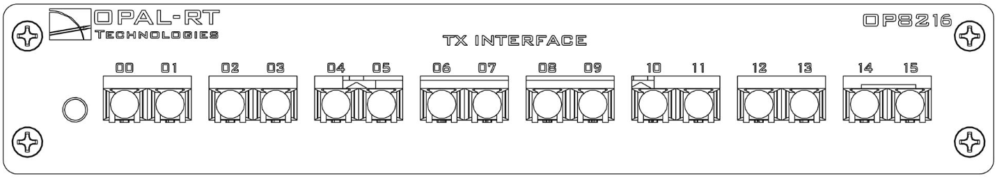
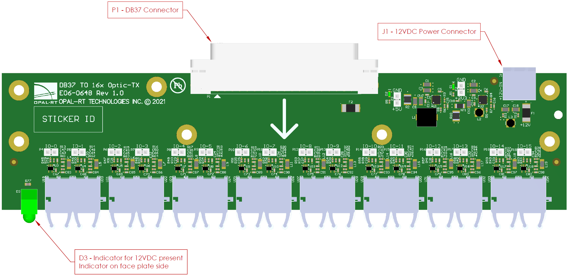
OP8216 - 16 Channels Output (Tx) - Front Plate
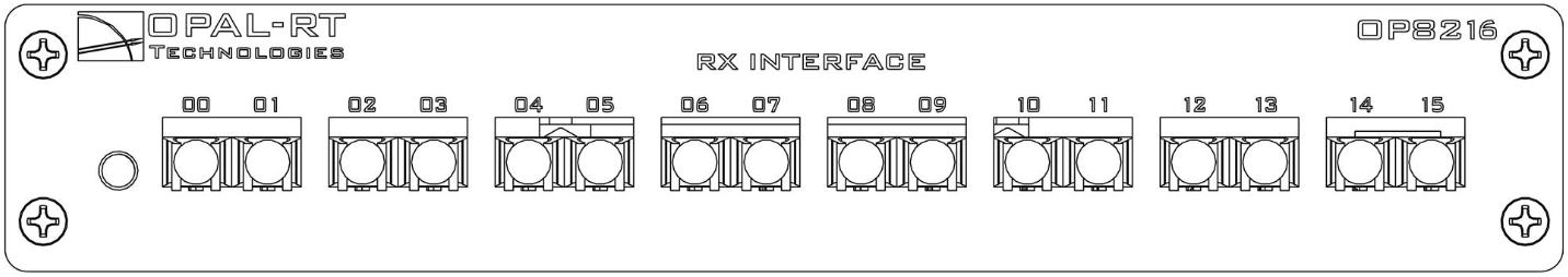
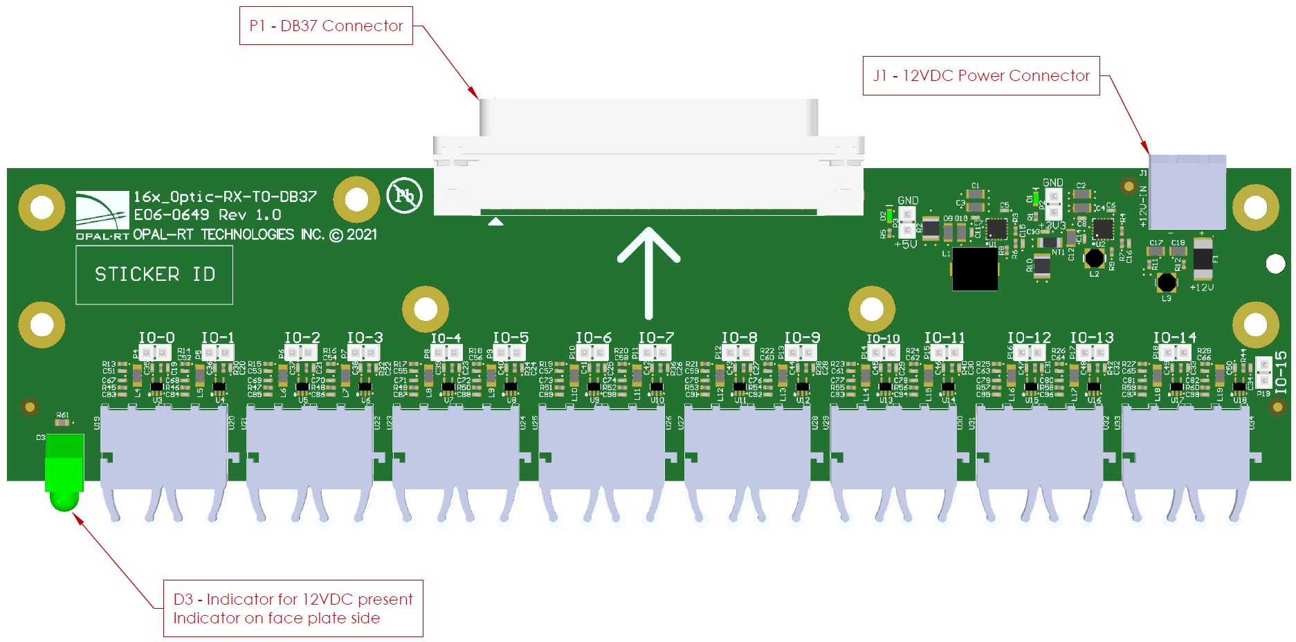
OP8216 - 16 Channels Input (Rx) - Front Plate
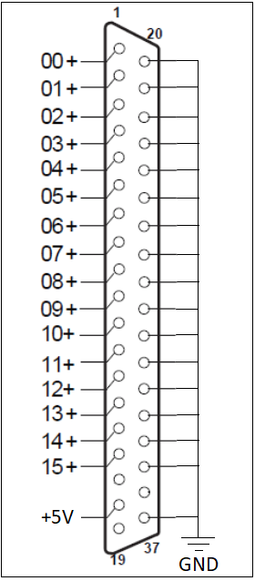
DB37 Pins Assignment
DB37 Connector | Channel and Signal Name | Screw Terminal Connector | DB37 Connector | Channel and Signal Name | Screw Terminal Connector | |
|---|---|---|---|---|---|---|
1 | +CH00 | +00 | 20 | GND | -00 |
|
2 | +CH01 | +01 | 21 | GND | -01 | |
3 | +CH02 | +02 | 22 | GND | -02 | |
4 | +CH03 | +03 | 23 | GND | -03 | |
5 | +CH04 | +04 | 24 | GND | -04 | |
6 | +CH05 | +05 | 25 | GND | -05 | |
7 | +CH06 | +06 | 26 | GND | -06 | |
8 | +CH07 | +07 | 27 | GND | -07 | |
9 | +CH08 | +08 | 28 | GND | -08 | |
10 | +CH09 | +09 | 29 | GND | -09 | |
11 | +CH10 | +10 | 30 | GND | -10 | |
12 | +CH11 | +11 | 31 | GND | -11 | |
13 | +CH12 | +12 | 32 | GND | -12 | |
14 | +CH13 | +13 | 33 | GND | -13 | |
15 | +CH14 | +14 | 34 | GND | -14 | |
16 | +CH15 | +15 | 35 | GND | -15 | |
17 | 36 | |||||
18 | +5V (out) | 37 | GND | |||
19 |
J1 - Power Connector Pin Assignment
Power Connector - J1 Connector | Signal Name | Comment |
|---|---|---|
1 | +12V | Silkscreen indication on pcb ( + ) |
2 | GND | Silkscreen indication on pcb ( - ) |
OP8216-16-1 PCB Connector View
OP8216-16-2 PCB Connector View
OPAL-RT TECHNOLOGIES, Inc. | 1751, rue Richardson, bureau 1060 | Montréal, Québec Canada H3K 1G6 | opal-rt.com | +1 514-935-2323
Follow OPAL-RT: LinkedIn | Facebook | YouTube | X/Twitter