Documentation Home Page ◇ Hardware Home Page
Pour la documentation en FRANÇAIS, utilisez l'outil de traduction de votre navigateur Chrome, Edge ou Safari. Voir un exemple.
OP4200 Hardware Interface
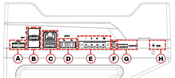
Side Connectors
- A: JTAG connector for ZYNQ programming (used in the event of lost or damaged configuration, this feature should only be used by qualified personnel).
B: SFP (small form-factor pluggable) ports controlled from the FPGA, for high-speed communication with other simulators' FPGAs or with third-party devices. Each socket controls one communication link. SFP transceivers and fiber optic cables must be selected according to the type and speed of the communication protocol implemented in the FPGA (OPAL-RT MUlti-System Expansion link (MuSE) link or third-party device connection).
Note
MuSE link requires the following specific SFP transceivers and optical fiber cable:
- SFP: Avago AFBR-57R5APZ
- Cable: LC-LC multimode 850nm optical fiber
- C: RJ45 (network connection) and USB 2.0 connectors
- D: Fiber optic connectors (Rx and Tx), used to synchronize the OP4200 with other
- E: Phoenix terminal power connector. Can be used with OP5972 power jack adapter
- F: Reset button
- G: DIP switches: Selects the position of the boot mode switches for various boot modes. See OP4200 Hardware Installation page for details
- H: Ground connector screw: attach the grounding wire to the nearest ground when using OP4200 in high risk environments
The OP4200 may be subject to EMI when installed in proximity to other devices.
OPAL-RT strongly recommends the use of anti-static wrist straps whenever handling any electronic device provided by OPAL-RT.
Damage resulting from electrostatic charges is not covered by the manufacturer’s warranty.
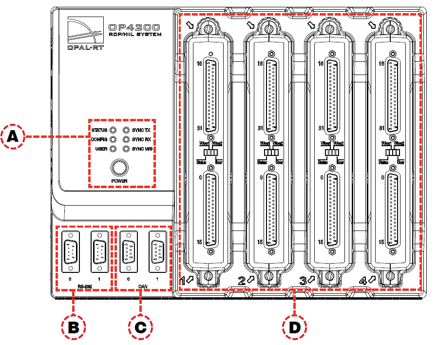
Rear Connectors
- A: Function LEDs and Power button: Press the power once to power up the unit. Press twice to shut down. The power button lights when the unit is powered up and functioning.
| Name | Color | Description |
|---|---|---|
| STATUS | Green Yellow | Indicates that the unit is powered up and functioning properly. Indicates a system error. |
| CONFIG | Green | Indicates that FPGA programming is complete. |
| USER | Green Yellow | User-configurable to display a condition specified by the user. If undefined, displays no status. |
| SYNC TX | Green | Indicates when unit transmits a synch signal |
| SYNC RX | Green | Indicates when unit receives a synch signal |
| SYNC M/S | Green Yellow | Lights yellow (at startup) when no model is loaded. Once a model is loaded, indicates the unit is in Master mode. For more information about the use of Vuser and Vrtn pleaser refer to this article in the OPAL-RT knowledge base : How to power the different DB37 boards for digital outputs. Indicates the unit is in Slave mode (the Use external synchronization source checkbox in OPAL-RT Board driver via allows the user to make the unit a slave). |
- B: RS232 connectors. Allow a direct connection to the host computer to display the OP4200 System Configuration IP address modification
- C: CAN connectors: CAN 2.0A, 2.0B, and ISO 118981-1 standard compliant
- D: I/O cassettes (see 4661440 for more details).
Cassettes
There are four cassettes slots, labeled 1 to 4, in the OP4200. The OP4200 standard configuration includes the following four cassettes:
| Slot 1 | OP4240-1, 16 analog inputs |
|---|---|
| Slot 2 | OP4230-1, 16 analog outputs |
| Slot 3 | OP4250-1, 32 digital inputs |
| Slot 4 | OP4260-1, 32 digital outputs. |
Digital cassettes have two DB37 connectors (one for channels 00-15 and one for channels 16-31), and analog cassettes have one DB37 connector (for channels 00-15).
See the OP4200 cassettes section for a description of these standard cassettes, and for other cassettes options.
Cassette LEDs
Each cassette has four LEDs, each used to indicate a specific status:
LED # | NAME | DESCRIPTION |
|---|---|---|
1 | Status | Blinking green: FPGA and hardware functioning normally. Blinking red: FPGA not responding, not sending heartbeat signal to cassette. Off: hardware malfunction in the cassette. |
2 | VUser1 (digital only) | Green = external Vuser present Red = no external Vuser present |
3 | VUser2 (digital only) | Green = Vuser present Red = no Vuser present |
4 | User | NOT USED |
For more information about the use of Vuser and Vrtn pleaser refer to this article in the OPAL-RT knowledge base : How to power the different DB37 boards for digital outputs.
OPAL-RT TECHNOLOGIES, Inc. | 1751, rue Richardson, bureau 1060 | Montréal, Québec Canada H3K 1G6 | opal-rt.com | +1 514-935-2323
Follow OPAL-RT: LinkedIn | Facebook | YouTube | X/Twitter

