Documentation Home Page ◇ Hardware Home Page
Pour la documentation en FRANÇAIS, utilisez l'outil de traduction de votre navigateur Chrome, Edge ou Safari. Voir un exemple.
OP4200 Hardware Installation
Basic Installation
Follow this simple installation procedure. Make sure to respect proper grounding:
- Place the OP4200 on a shelf
- Connect the power cable to the nearest power outlet
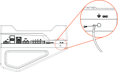
- If using in high-risk tests or environment, connect the ground screw as described in the4661497 section below
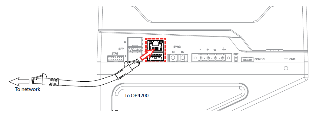
- Connect the RJ45 cable from the OP4200 to a network
OPAL-RT strongly recommends the use of anti-static wrist straps whenever handling any electronic device provided by OPAL-RT. Damage resulting from electrostatic charges is not covered by the manufacturer’s warranty.
Disconnect power before servicing.
The OP4200 may be subjected to EMI when installed in proximity to other devices. Make sure to connect the OP4200 to the nearest ground to prevent any EMI related damage to the simulator.
General Cabling Instructions
The OP4200 provides a number of connectors that each allow users a specific interaction with the unit. Some connections are necessary to operate the OP4200, while others provide optional features and interactions. This section presents the necessary connections first, then provides instructions for optional connections.
Connecting the Power Cable
The power cable is connected to the OP4200 using a special adaptor (OP5972).
- Press the power adapter box firmly into the phoenix connector on the OP4200
- Insert power supply connector into adapter box, as
- Plug power cable into the appropriate source (outlet).
Do not insert the power cord into the Vuser* 24V output (square connector on OP5972 power jack adaptor). This may damage all connected devices.
Make sure to insert the power cord connector into the round connector on the power jack adaptor
* For more information about the use of Vuser and Vrtn pleaser refer to this article in the OPAL-RT knowledge base : How to power the different DB37 boards for digital outputs.
Connecting the Ground Screw
If you are working on high-risk tests or in a high-risk environment, connect a grounding cable from the OP4200 ground screw to ensure that it terminates securely in a ground.
Proper grounding helps prevent electric shocks, protects the OP4200 from voltage spikes (from a variety of causes, including lightning strikes), and provides increased immunity from EMI by lowering noise levels and emissions.
- Select a flat braided grounding strap of adequate length (as short as possible provides the best protection), with ring terminals on each end
- Attach one ring terminal to the ground screw on the OP4200
- Attach the other ring terminal to the nearest ground source using a nut and lock washer
Connecting The Network Cable
Before connecting your OP4200 to your network, verify the IP address with your IT department. You may need to change the simulator IP address to correspond to available addresses on your network.
The OP4200 simulator offers quick, single-ended connections, through RJ45. The network cable must only be connected to the standard network jack.
Do not plug the network cable into any jack other than the jack intended for that purpose.
Initial Setup
Although the OP4200 is configured to function right out of the package, there are a few configurations that may be necessary (or desired) based on your network setup or according to your specific parameters. This section deals with how to modify those parameters before you proceed to use your OP4200.
DIP Switch Configurations
This feature should be reserved for qualified OPAL-RT personnel.
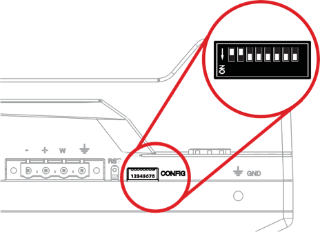
DIP switches on the OP4200 set various boot and operation parameters.
After a Reset, the boot mode switches are read to determine the primary boot device used (default mode is boot from SD card).
SW # | Description | Functionality | |
|---|---|---|---|
1/2 | Boot mode 0/1 | Used in conjunction with switch #2, this selects the device to read at boot: Boot Device Boot Mode 1 Boot Mode 0 JTAG ON ON NAND ON OFF QSPI OFF ON uSD Card OFF OFF (default position) | 1 2 3 4 5 6 7 8 ON = down, Off = up |
3 | Console Enable Service | When set to ON, RS232 port 0 is set in terminal mode | |
4 | N/A | NOT USED | |
5 | CAN1 Termination | When set to ON the 120 ohm CAN termination is enabled for CAN port 0 | |
6 | CAN2 Termination | When set to ON the 120 ohm CAN termination is enabled for CAN port 1 | |
7 | N/A | NOT USED | |
8 | N/A | NOT USED | |
Changing the IP Address
The OP4200 pre-configured with an IP address (an identifying label is attached to the unit), but it may conflict with your network infrastructure; you may need to change the IP address for your OP4200. The best way to do this is to directly connect your OP4200 to your host computer (laptop, etc.). (Be sure to contact your IT department to obtain a valid IP address from them).
Before you begin, make sure your computer has a serial terminal program installed; you need it to access the OP4200 Recovery application. If there is no serial terminal installed, you must install one (such as MobaXterm) to access the OP4200 configuration application.
The RS232 cable enables users to connect the OP4200 to a PC to access the IP address modification interface. It also allows users to perform various troubleshooting or reflashing activities.
- Connect the USB connector to a computer or laptop. Wait for the computer to discover the new machine.
- Connect the RS232 connector end to the RS-232 (port 0) connector on the OP4200
- Install the serial terminal application (MobaXterm) on your computer:
- Using an internet browser go to MobaTek’s mobaXtem website: http://mobaxterm.mobatek.net/.
- Click the Download section
- Select the Home Edition version of MobaXterm and Click Download Now
- Select the Portable edition of MobaXterm Home edition
- Save the file to a known location on your machine.
- Extract the contents of the zip file and double click the extracted executable of MobaXterm i.e.: “MobaXterm_Personal_9.4.exe” the program will start.
- In MobaXterm:
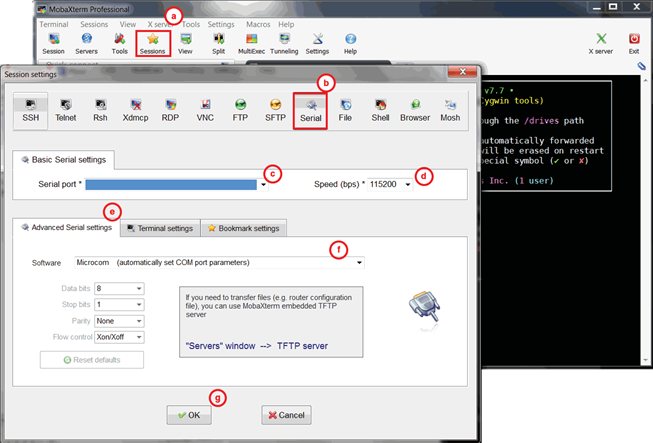
- Click the Sessions button to start a new session
- In the Session Settings window, Click the Serial Button
Starting a serial session in MobaXterm
| C | Select the serial (COM) port to which the OP4200 is connected (it should appear automatically in the list) |
|---|---|
| D | Set the Speed to 115200 |
| E | Click the Advanced settings tab |
| F | For the Serial engine field, select “Microcom” to have the rest of the parameters selected automatically |
| G | Click OK to start the session
|
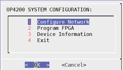
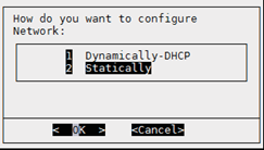
In the next screen, select 2 Statically and click OK.
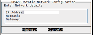
Type the following information in the next screen: IP address, Netmask and Gateway (your IT department should provide you with the information).
Click Submit. A confirmation screen appears
Click OK to return to the main menu. Click 4 Exit and close MobaXterm.
Your OP4200 is now ready to use and can be connected to your network. Once it is connected to the network, test communication by pinging the OP4200 from your computer
Changing the IP Address Permanently using Mobaxterm: Alternate Methods
The serial communication method to change the IP address outlined above is appropriate when users don't yet know the IP address. For example, you may have just received your OP4200.
You may however already know the IP address, and need to change it permanently.
To change the OP4200's IP address permanently, please follow these steps:
In the OP4200 terminal from Mobaxterm, run the "config" command to launch the OP4200's configuration settings. You will have the option to configure the IP address permanently.
- follow the steps related to OP4200 system configuration GUI mentionned just above (end of the section Changing the IP Address)
OPAL-RT TECHNOLOGIES, Inc. | 1751, rue Richardson, bureau 1060 | Montréal, Québec Canada H3K 1G6 | opal-rt.com | +1 514-935-2323
Follow OPAL-RT: LinkedIn | Facebook | YouTube | X/Twitter

