Documentation Home Page ◇ RT-LAB Home Page
Pour la documentation en FRANÇAIS, utilisez l'outil de traduction de votre navigateur Chrome, Edge ou Safari. Voir un exemple.
Connecting Your Simulator and Creating Your First Project
- Sylvain Ménard
It is now time to unpack your real-time simulator (also called target in this document).
For the first connection, to configure your target, we recommend that you have your IT department set up your simulator’s IP address and ensure that the firewall will not interfere with or block RT-LAB.
Consult the Installation Guide for additional details (C:\OPAL-RT\RT-LAB\versionxx.x\help\pdf\RT-LAB_ IG.pdf (example assumes that RT-LAB was installed on the C drive of your computer)).
Using RT-LAB
Before using RT-LAB, you must configure the target. This section describes the basic tools and steps to setup RT-LAB and runs a sample model.
Toolbar
In addition to the standard menu items, RT-LAB provides a toolbar of quick access buttons to do many of the tasks in one click:

Build
| Build (Compile) a model or manage build configurations |
|---|---|
Assign
| Opens the assignation page of a model editor |
Load
| Loads a model |
Execute
| Executes a model |
Pause
| Pauses a model |
Reset
| Stops a model |
In the Project Explorer, double-click to discover new targets; this process may take some time. Once RT-LAB detects targets, the Detected RT-LAB Targets window appears. Select the target you want to use and click Finish.

Discovering targets
Edit the name assigned to your simulator (in the Overview window), as desired, and click Finish.
Note: If your simulator is not automatically detected, please refer to the My simulator is not detected by RT-LAB Troubleshooting section.
Your simulator is now available in the RT-LAB interface.
Create Your First Project
STEP 1: Create a new project based on an example model
- In the RT-LAB Project Explorer, double-click Create a new project...
- Name your project (e.g. My first Project) then click Next.

Creating a new project
The next window that appears allows you to select the model for the project. Select rtdemo1 for your first project.

RT-Demo1 example
- Browse the model directory and select the Basic folder and then select rtdemo1.
- Click Finish.
Your project is now available in the Project Explorer. It contains a simple model named rtdemo1. This model simulates a mass-spring-damper mechanical system with its PID controller.
STEP 2: Build the model
The build process allows RT-LAB to transform the Simulink model into a full real-time simulation. This process must be repeated each time the Simulink model is modified.
- In the Project Explorer window, expand the project you just created to find the rtdemo1F model.
- Drag the model onto your target. This will automatically configure your model to run on this particular target.

Right-click on the model, then select Simulation > Build configurations… This opens the build configurations window
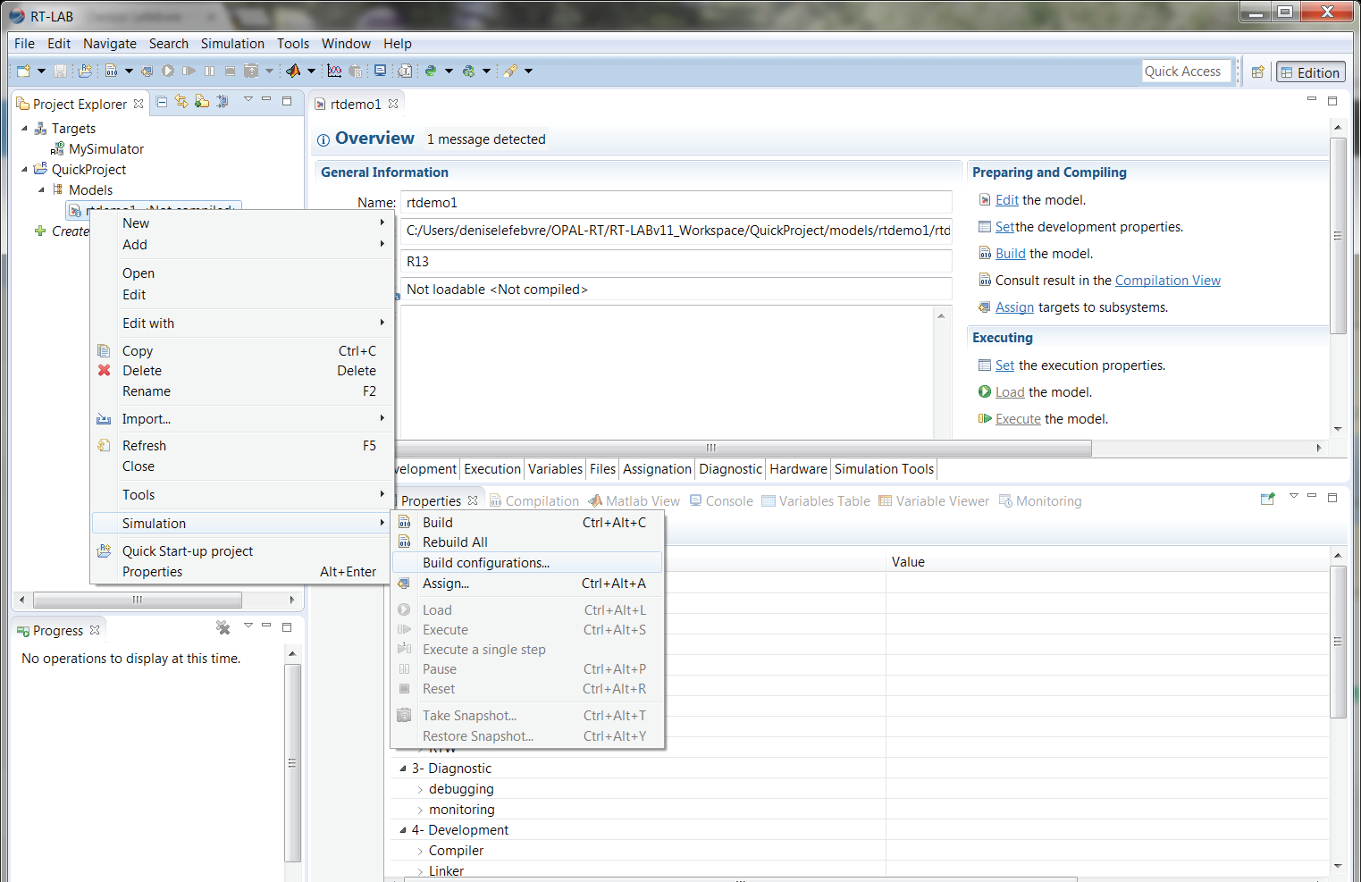
In the Build Configurations window, select the MATLAB version to use from the drop-down list

Building the model
- Verify that your target is set as the Development Node. The Development Node is the target that RT-LAB will use to perform the build. (To set as Development node, right-click the target and select Set as development node.)
- Click OK then wait for the build process to complete. You can view the progress of the build in the Compilation View at the bottom of the RT-LAB interface.
STEP 3: Load the Model
The load process prepares the real-time target to perform the simulation.
- Click the Load toolbar button.
Note: It may take a few moments for the model to load. When it has loaded, the rtdemo1_2_sc_user_interface Simulink console window appears.

Simulink console
STEP 4: Execute the Model
Executing the model starts the real-time simulation on the target.
- Click the Execute toolbar button.
STEP 5: Use the Console to Interact With the Simulation
The user console (Figure 9) is now receiving and sending data to the simulation. Double-click a scope block to observe the simulation and see any changes live in the scope viewer (Figure 11).
Double-click the adjust reference block ![]() to modify the set point of the mass-spring-damper system and double-click the scope blocks to observe signals received from the simulator.
to modify the set point of the mass-spring-damper system and double-click the scope blocks to observe signals received from the simulator.

Adjusting the reference to view changes in scope

Observing simulation results and changes in the scope
STEP 6: Stop the Simulation
Stopping the simulation releases the target (makes it available for use) and allows for another simulation to be performed.
- Click the Reset toolbar button to stop the simulation.
- Verify that the console is automatically closed. You are now ready to test your integration model.
OPAL-RT TECHNOLOGIES, Inc. | 1751, rue Richardson, bureau 1060 | Montréal, Québec Canada H3K 1G6 | opal-rt.com | +1 514-935-2323
Follow OPAL-RT: LinkedIn | Facebook | YouTube | X/Twitter