Documentation Home Page ◇ Hardware Home Page
Pour la documentation en FRANÇAIS, utilisez l'outil de traduction de votre navigateur Chrome, Edge ou Safari. Voir un exemple.
OP8665 Interfaces Description
Front Casing Interface
| A | DIGITAL IN | 32 channels split over two DB37 male connectors. Each connector can be connected to the digital input channels of the OPAL-RT real-time simulator via a pin to pin DB37 female to male cable |
|---|---|---|
| B | DIGITAL OUT | 32 channels split over two DB37 male connectors. Each connector can be connected to the digital output channels of the OPAL-RT real-time simulator via a pin to pin DB37 female to male cable |
| C | CAN BUS ONLY | 2 DB9 female connectors |
| D | ANALOG IN | Each connector can be connected to the analog output channels of the OPAL-RT real-time simulator via a pin to pin DB37 female to male cable |
| E | ANALOG OUT | Each connector can be connected to the analog input channels of the OPAL-RT real-time simulator via a pin to pin DB37 female to male cable. |
Controller Interface Board
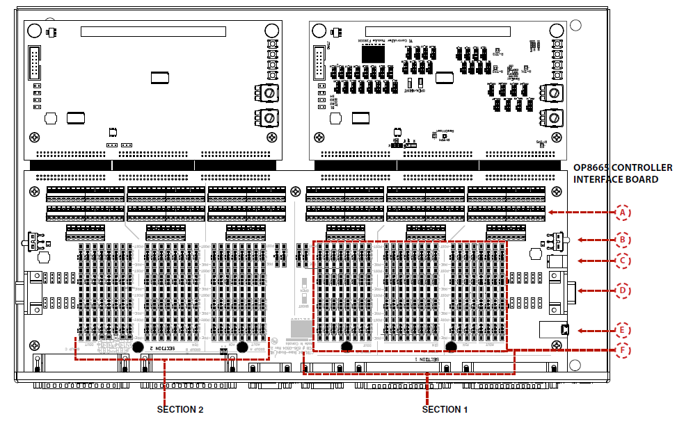
The controller interface is divided into two identical sections: Section 1 on the right and Section 2 on the left. Each section can connect to one controller board. A single power source, located in Section 1, is used for both sections. The signals from the DB37 are equally distributed between both sections, according to the Pin Assignments table.
| A | Screw terminal area | connect to probe signals |
|---|---|---|
| B | Power On/Off Switch | 1 for each section, with green status LED |
| C | Power Input | 12V connector in Section 1 powers both sections |
| D | RS232 | 1 DB9 female for each section |
| E | USB to UART Adaptor | 1 USB connector for each section, with green status LED |
| F | TestPoint Area |
Test Point Area
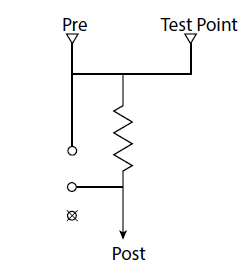
By default, the OP8665 board has a probing area providing test points with an integrated 0 Ohm resistor: the user can probe the signals either before (PRE, HIL side) or after (POST, controller side) the signal break.
The OP8665 controller interface also has an available option to add a breakout area (with pins and jumpers) to open or short a signal. The user can move the jumper to an open/short position to simulate faults or to jump a signal.
OPAL-RT TECHNOLOGIES, Inc. | 1751, rue Richardson, bureau 1060 | Montréal, Québec Canada H3K 1G6 | opal-rt.com | +1 514-935-2323
Follow OPAL-RT: LinkedIn | Facebook | YouTube | X/Twitter


