Documentation Home Page ◇ HYPERSIM Home Page
Pour la documentation en FRANÇAIS, utilisez l'outil de traduction de votre navigateur Chrome, Edge ou Safari. Voir un exemple.
Misc. | AMOD
MODAL ANALYSIS – [AMOD]
This function outputs modal analysis of a single input signal.
CATEGORY
Miscellaneous
DESCRIPTION
The modal analysis returns the dynamic parameters containing the amplitude, damping, frequency, phase shift and damping ratio of each complex mode identified in the input signal by processing it through an ERA/Prony algorithm method.
To return the modal analysis results, the analyzed input signal is presumed as the impulse-response of a black-box dynamic state-space system. The system identification of this dynamic system is obtained by applying the Eigensystem realization algorithm (ERA) based on Hankel matrices, singular value decomposition and Markov parameters calculation to the input signal. From this system identification, the Prony approach algorithm is then applied to obtain the dynamic parameters based on the system’s equation and residual terms calculation.
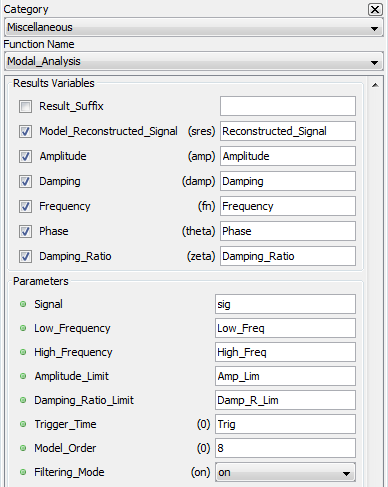
RESULT VARIABLES AND PARAMETERS
| Model Reconstructed Signal | Input signal reconstructed with the dynamic parameters from the k complex mode identified in the analysis |
| Amplitude | Modal amplitude [ak] |
| Damping | Modal damping value [σk] |
| Frequency | Modal frequency [fk] |
| Phase | Phase shift [ϴk] |
| Damping Ratio | Modal relative damping ratio [ζk] |
| Signal | The input signal to be analyzed |
| Low Frequency | Low-frequency limit for oscillatory modes for the input signal. This limit must be set so there is at least a complete period in the window selected for analysis. |
It must respect the following:
' aria-hidden='true'%3e %3cg transform='translate(167%2c0)'%3e %3cg transform='translate(-11%2c0)'%3e %3cg transform='translate(0%2c-3)'%3e %3cuse xlink:href='%23E1-MJMAIN-30'%3e%3c/use%3e %3cuse xlink:href='%23E1-MJMAIN-2E' x='500' y='0'%3e%3c/use%3e %3cuse xlink:href='%23E1-MJMAIN-30' x='779' y='0'%3e%3c/use%3e %3cuse xlink:href='%23E1-MJMAIN-35' x='1279' y='0'%3e%3c/use%3e %3cuse xlink:href='%23E1-MJMATHI-48' x='1780' y='0'%3e%3c/use%3e %3cuse xlink:href='%23E1-MJMATHI-7A' x='2668' y='0'%3e%3c/use%3e %3cuse xlink:href='%23E1-MJMAIN-2264' x='3414' y='0'%3e%3c/use%3e %3cg transform='translate(4471%2c0)'%3e %3cuse xlink:href='%23E1-MJMATHI-66' x='0' y='0'%3e%3c/use%3e %3cg transform='translate(490%2c-150)'%3e %3cuse transform='scale(0.707)' xlink:href='%23E1-MJMATHI-6C' x='0' y='0'%3e%3c/use%3e %3cuse transform='scale(0.707)' xlink:href='%23E1-MJMATHI-6F' x='298' y='0'%3e%3c/use%3e %3cuse transform='scale(0.707)' xlink:href='%23E1-MJMATHI-77' x='784' y='0'%3e%3c/use%3e %3c/g%3e %3c/g%3e %3cuse xlink:href='%23E1-MJMAIN-2264' x='6400' y='0'%3e%3c/use%3e %3cg transform='translate(7456%2c0)'%3e %3cuse xlink:href='%23E1-MJMATHI-66' x='0' y='0'%3e%3c/use%3e %3cg transform='translate(490%2c-150)'%3e %3cuse transform='scale(0.707)' xlink:href='%23E1-MJMATHI-68' x='0' y='0'%3e%3c/use%3e %3cuse transform='scale(0.707)' xlink:href='%23E1-MJMATHI-69' x='576' y='0'%3e%3c/use%3e %3cuse transform='scale(0.707)' xlink:href='%23E1-MJMATHI-67' x='922' y='0'%3e%3c/use%3e %3cuse transform='scale(0.707)' xlink:href='%23E1-MJMATHI-68' x='1402' y='0'%3e%3c/use%3e %3c/g%3e %3c/g%3e %3c/g%3e %3c/g%3e %3c/g%3e %3c/g%3e %3c/svg%3e)
|
High Frequency: High-frequency limit for oscillatory modes for the input signal. It must be defined in a way so undersampling is avoided:
' aria-hidden='true'%3e %3cg transform='translate(167%2c0)'%3e %3cg transform='translate(-11%2c0)'%3e %3cg transform='translate(0%2c38)'%3e %3cuse xlink:href='%23E1-MJMATHI-66' x='0' y='0'%3e%3c/use%3e %3cg transform='translate(490%2c-150)'%3e %3cuse transform='scale(0.707)' xlink:href='%23E1-MJMATHI-68' x='0' y='0'%3e%3c/use%3e %3cuse transform='scale(0.707)' xlink:href='%23E1-MJMATHI-69' x='576' y='0'%3e%3c/use%3e %3cuse transform='scale(0.707)' xlink:href='%23E1-MJMATHI-67' x='922' y='0'%3e%3c/use%3e %3cuse transform='scale(0.707)' xlink:href='%23E1-MJMATHI-68' x='1402' y='0'%3e%3c/use%3e %3c/g%3e %3cuse xlink:href='%23E1-MJMAIN-2264' x='2267' y='0'%3e%3c/use%3e %3cg transform='translate(3046%2c0)'%3e %3cg transform='translate(397%2c0)'%3e %3crect stroke='none' width='7091' height='60' x='0' y='220'%3e%3c/rect%3e %3cuse xlink:href='%23E1-MJMAIN-31' x='3295' y='676'%3e%3c/use%3e %3cg transform='translate(60%2c-716)'%3e %3cuse xlink:href='%23E1-MJMAIN-34'%3e%3c/use%3e %3cuse xlink:href='%23E1-MJMAIN-2E' x='500' y='0'%3e%3c/use%3e %3cuse xlink:href='%23E1-MJMATHI-73' x='779' y='0'%3e%3c/use%3e %3cuse xlink:href='%23E1-MJMATHI-61' x='1248' y='0'%3e%3c/use%3e %3cuse xlink:href='%23E1-MJMATHI-6D' x='1778' y='0'%3e%3c/use%3e %3cuse xlink:href='%23E1-MJMATHI-70' x='2656' y='0'%3e%3c/use%3e %3cuse xlink:href='%23E1-MJMATHI-6C' x='3160' y='0'%3e%3c/use%3e %3cuse xlink:href='%23E1-MJMATHI-69' x='3458' y='0'%3e%3c/use%3e %3cuse xlink:href='%23E1-MJMATHI-6E' x='3804' y='0'%3e%3c/use%3e %3cuse xlink:href='%23E1-MJMATHI-67' x='4404' y='0'%3e%3c/use%3e %3cuse xlink:href='%23E1-MJMATHI-72' x='5162' y='0'%3e%3c/use%3e %3cuse xlink:href='%23E1-MJMATHI-61' x='5614' y='0'%3e%3c/use%3e %3cuse xlink:href='%23E1-MJMATHI-74' x='6143' y='0'%3e%3c/use%3e %3cuse xlink:href='%23E1-MJMATHI-65' x='6505' y='0'%3e%3c/use%3e %3c/g%3e %3c/g%3e %3c/g%3e %3c/g%3e %3c/g%3e %3c/g%3e %3c/g%3e %3c/svg%3e)
|
Amplitude Limit: Proportional maximum between the highest and lowest amplitudes of oscillatory mode displayed.
%5cend%7barray%7d%3c/title%3e %3cdefs aria-hidden='true'%3e %3cpath stroke-width='1' id='E1-MJMATHI-61' d='M33 157Q33 258 109 349T280 441Q331 441 370 392Q386 422 416 422Q429 422 439 414T449 394Q449 381 412 234T374 68Q374 43 381 35T402 26Q411 27 422 35Q443 55 463 131Q469 151 473 152Q475 153 483 153H487Q506 153 506 144Q506 138 501 117T481 63T449 13Q436 0 417 -8Q409 -10 393 -10Q359 -10 336 5T306 36L300 51Q299 52 296 50Q294 48 292 46Q233 -10 172 -10Q117 -10 75 30T33 157ZM351 328Q351 334 346 350T323 385T277 405Q242 405 210 374T160 293Q131 214 119 129Q119 126 119 118T118 106Q118 61 136 44T179 26Q217 26 254 59T298 110Q300 114 325 217T351 328Z'%3e%3c/path%3e %3cpath stroke-width='1' id='E1-MJMATHI-6B' d='M121 647Q121 657 125 670T137 683Q138 683 209 688T282 694Q294 694 294 686Q294 679 244 477Q194 279 194 272Q213 282 223 291Q247 309 292 354T362 415Q402 442 438 442Q468 442 485 423T503 369Q503 344 496 327T477 302T456 291T438 288Q418 288 406 299T394 328Q394 353 410 369T442 390L458 393Q446 405 434 405H430Q398 402 367 380T294 316T228 255Q230 254 243 252T267 246T293 238T320 224T342 206T359 180T365 147Q365 130 360 106T354 66Q354 26 381 26Q429 26 459 145Q461 153 479 153H483Q499 153 499 144Q499 139 496 130Q455 -11 378 -11Q333 -11 305 15T277 90Q277 108 280 121T283 145Q283 167 269 183T234 206T200 217T182 220H180Q168 178 159 139T145 81T136 44T129 20T122 7T111 -2Q98 -11 83 -11Q66 -11 57 -1T48 16Q48 26 85 176T158 471L195 616Q196 629 188 632T149 637H144Q134 637 131 637T124 640T121 647Z'%3e%3c/path%3e %3cpath stroke-width='1' id='E1-MJMAIN-2265' d='M83 616Q83 624 89 630T99 636Q107 636 253 568T543 431T687 361Q694 356 694 346T687 331Q685 329 395 192L107 56H101Q83 58 83 76Q83 77 83 79Q82 86 98 95Q117 105 248 167Q326 204 378 228L626 346L360 472Q291 505 200 548Q112 589 98 597T83 616ZM84 -118Q84 -108 99 -98H678Q694 -104 694 -118Q694 -130 679 -138H98Q84 -131 84 -118Z'%3e%3c/path%3e %3cpath stroke-width='1' id='E1-MJMAIN-28' d='M94 250Q94 319 104 381T127 488T164 576T202 643T244 695T277 729T302 750H315H319Q333 750 333 741Q333 738 316 720T275 667T226 581T184 443T167 250T184 58T225 -81T274 -167T316 -220T333 -241Q333 -250 318 -250H315H302L274 -226Q180 -141 137 -14T94 250Z'%3e%3c/path%3e %3cpath stroke-width='1' id='E1-MJMATHI-6D' d='M21 287Q22 293 24 303T36 341T56 388T88 425T132 442T175 435T205 417T221 395T229 376L231 369Q231 367 232 367L243 378Q303 442 384 442Q401 442 415 440T441 433T460 423T475 411T485 398T493 385T497 373T500 364T502 357L510 367Q573 442 659 442Q713 442 746 415T780 336Q780 285 742 178T704 50Q705 36 709 31T724 26Q752 26 776 56T815 138Q818 149 821 151T837 153Q857 153 857 145Q857 144 853 130Q845 101 831 73T785 17T716 -10Q669 -10 648 17T627 73Q627 92 663 193T700 345Q700 404 656 404H651Q565 404 506 303L499 291L466 157Q433 26 428 16Q415 -11 385 -11Q372 -11 364 -4T353 8T350 18Q350 29 384 161L420 307Q423 322 423 345Q423 404 379 404H374Q288 404 229 303L222 291L189 157Q156 26 151 16Q138 -11 108 -11Q95 -11 87 -5T76 7T74 17Q74 30 112 181Q151 335 151 342Q154 357 154 369Q154 405 129 405Q107 405 92 377T69 316T57 280Q55 278 41 278H27Q21 284 21 287Z'%3e%3c/path%3e %3cpath stroke-width='1' id='E1-MJMATHI-78' d='M52 289Q59 331 106 386T222 442Q257 442 286 424T329 379Q371 442 430 442Q467 442 494 420T522 361Q522 332 508 314T481 292T458 288Q439 288 427 299T415 328Q415 374 465 391Q454 404 425 404Q412 404 406 402Q368 386 350 336Q290 115 290 78Q290 50 306 38T341 26Q378 26 414 59T463 140Q466 150 469 151T485 153H489Q504 153 504 145Q504 144 502 134Q486 77 440 33T333 -11Q263 -11 227 52Q186 -10 133 -10H127Q78 -10 57 16T35 71Q35 103 54 123T99 143Q142 143 142 101Q142 81 130 66T107 46T94 41L91 40Q91 39 97 36T113 29T132 26Q168 26 194 71Q203 87 217 139T245 247T261 313Q266 340 266 352Q266 380 251 392T217 404Q177 404 142 372T93 290Q91 281 88 280T72 278H58Q52 284 52 289Z'%3e%3c/path%3e %3cpath stroke-width='1' id='E1-MJMATHI-41' d='M208 74Q208 50 254 46Q272 46 272 35Q272 34 270 22Q267 8 264 4T251 0Q249 0 239 0T205 1T141 2Q70 2 50 0H42Q35 7 35 11Q37 38 48 46H62Q132 49 164 96Q170 102 345 401T523 704Q530 716 547 716H555H572Q578 707 578 706L606 383Q634 60 636 57Q641 46 701 46Q726 46 726 36Q726 34 723 22Q720 7 718 4T704 0Q701 0 690 0T651 1T578 2Q484 2 455 0H443Q437 6 437 9T439 27Q443 40 445 43L449 46H469Q523 49 533 63L521 213H283L249 155Q208 86 208 74ZM516 260Q516 271 504 416T490 562L463 519Q447 492 400 412L310 260L413 259Q516 259 516 260Z'%3e%3c/path%3e %3cpath stroke-width='1' id='E1-MJMATHI-70' d='M23 287Q24 290 25 295T30 317T40 348T55 381T75 411T101 433T134 442Q209 442 230 378L240 387Q302 442 358 442Q423 442 460 395T497 281Q497 173 421 82T249 -10Q227 -10 210 -4Q199 1 187 11T168 28L161 36Q160 35 139 -51T118 -138Q118 -144 126 -145T163 -148H188Q194 -155 194 -157T191 -175Q188 -187 185 -190T172 -194Q170 -194 161 -194T127 -193T65 -192Q-5 -192 -24 -194H-32Q-39 -187 -39 -183Q-37 -156 -26 -148H-6Q28 -147 33 -136Q36 -130 94 103T155 350Q156 355 156 364Q156 405 131 405Q109 405 94 377T71 316T59 280Q57 278 43 278H29Q23 284 23 287ZM178 102Q200 26 252 26Q282 26 310 49T356 107Q374 141 392 215T411 325V331Q411 405 350 405Q339 405 328 402T306 393T286 380T269 365T254 350T243 336T235 326L232 322Q232 321 229 308T218 264T204 212Q178 106 178 102Z'%3e%3c/path%3e %3cpath stroke-width='1' id='E1-MJMAIN-2E' d='M78 60Q78 84 95 102T138 120Q162 120 180 104T199 61Q199 36 182 18T139 0T96 17T78 60Z'%3e%3c/path%3e %3cpath stroke-width='1' id='E1-MJMATHI-6C' d='M117 59Q117 26 142 26Q179 26 205 131Q211 151 215 152Q217 153 225 153H229Q238 153 241 153T246 151T248 144Q247 138 245 128T234 90T214 43T183 6T137 -11Q101 -11 70 11T38 85Q38 97 39 102L104 360Q167 615 167 623Q167 626 166 628T162 632T157 634T149 635T141 636T132 637T122 637Q112 637 109 637T101 638T95 641T94 647Q94 649 96 661Q101 680 107 682T179 688Q194 689 213 690T243 693T254 694Q266 694 266 686Q266 675 193 386T118 83Q118 81 118 75T117 65V59Z'%3e%3c/path%3e %3cpath stroke-width='1' id='E1-MJMATHI-69' d='M184 600Q184 624 203 642T247 661Q265 661 277 649T290 619Q290 596 270 577T226 557Q211 557 198 567T184 600ZM21 287Q21 295 30 318T54 369T98 420T158 442Q197 442 223 419T250 357Q250 340 236 301T196 196T154 83Q149 61 149 51Q149 26 166 26Q175 26 185 29T208 43T235 78T260 137Q263 149 265 151T282 153Q302 153 302 143Q302 135 293 112T268 61T223 11T161 -11Q129 -11 102 10T74 74Q74 91 79 106T122 220Q160 321 166 341T173 380Q173 404 156 404H154Q124 404 99 371T61 287Q60 286 59 284T58 281T56 279T53 278T49 278T41 278H27Q21 284 21 287Z'%3e%3c/path%3e %3cpath stroke-width='1' id='E1-MJMAIN-29' d='M60 749L64 750Q69 750 74 750H86L114 726Q208 641 251 514T294 250Q294 182 284 119T261 12T224 -76T186 -143T145 -194T113 -227T90 -246Q87 -249 86 -250H74Q66 -250 63 -250T58 -247T55 -238Q56 -237 66 -225Q221 -64 221 250T66 725Q56 737 55 738Q55 746 60 749Z'%3e%3c/path%3e %3c/defs%3e %3cg stroke='currentColor' fill='currentColor' stroke-width='0' transform='matrix(1 0 0 -1 0 0)' aria-hidden='true'%3e %3cg transform='translate(167%2c0)'%3e %3cg transform='translate(-11%2c0)'%3e %3cg transform='translate(0%2c155)'%3e %3cuse xlink:href='%23E1-MJMATHI-61' x='0' y='0'%3e%3c/use%3e %3cuse transform='scale(0.707)' xlink:href='%23E1-MJMATHI-6B' x='748' y='-213'%3e%3c/use%3e %3cuse xlink:href='%23E1-MJMAIN-2265' x='1276' y='0'%3e%3c/use%3e %3cuse xlink:href='%23E1-MJMAIN-28' x='2332' y='0'%3e%3c/use%3e %3cg transform='translate(2721%2c0)'%3e %3cg transform='translate(120%2c0)'%3e %3crect stroke='none' width='4220' height='60' x='0' y='220'%3e%3c/rect%3e %3cg transform='translate(771%2c677)'%3e %3cuse xlink:href='%23E1-MJMATHI-61' x='0' y='0'%3e%3c/use%3e %3cg transform='translate(529%2c-150)'%3e %3cuse transform='scale(0.707)' xlink:href='%23E1-MJMATHI-6B' x='0' y='0'%3e%3c/use%3e %3cuse transform='scale(0.707)' xlink:href='%23E1-MJMATHI-6D' x='914' y='0'%3e%3c/use%3e %3cuse transform='scale(0.707)' xlink:href='%23E1-MJMATHI-61' x='1792' y='0'%3e%3c/use%3e %3cuse transform='scale(0.707)' xlink:href='%23E1-MJMATHI-78' x='2322' y='0'%3e%3c/use%3e %3c/g%3e %3c/g%3e %3cg transform='translate(60%2c-737)'%3e %3cuse xlink:href='%23E1-MJMATHI-41' x='0' y='0'%3e%3c/use%3e %3cuse xlink:href='%23E1-MJMATHI-6D' x='750' y='0'%3e%3c/use%3e %3cuse xlink:href='%23E1-MJMATHI-70' x='1629' y='0'%3e%3c/use%3e %3cuse xlink:href='%23E1-MJMAIN-2E' x='2132' y='0'%3e%3c/use%3e %3cuse xlink:href='%23E1-MJMATHI-6C' x='2577' y='0'%3e%3c/use%3e %3cuse xlink:href='%23E1-MJMATHI-69' x='2876' y='0'%3e%3c/use%3e %3cuse xlink:href='%23E1-MJMATHI-6D' x='3221' y='0'%3e%3c/use%3e %3c/g%3e %3c/g%3e %3c/g%3e %3cuse xlink:href='%23E1-MJMAIN-29' x='7181' y='0'%3e%3c/use%3e %3c/g%3e %3c/g%3e %3c/g%3e %3c/g%3e %3c/svg%3e)
|
' aria-hidden='true'%3e %3cg transform='translate(167%2c0)'%3e %3cg transform='translate(-11%2c0)'%3e %3cg transform='translate(0%2c-50)'%3e %3cuse xlink:href='%23E1-MJMAIN-31' x='0' y='0'%3e%3c/use%3e %3cuse xlink:href='%23E1-MJMAIN-2264' x='778' y='0'%3e%3c/use%3e %3cg transform='translate(1834%2c0)'%3e %3cuse xlink:href='%23E1-MJMATHI-61' x='0' y='0'%3e%3c/use%3e %3cuse transform='scale(0.707)' xlink:href='%23E1-MJMATHI-6B' x='748' y='-213'%3e%3c/use%3e %3c/g%3e %3cuse xlink:href='%23E1-MJMAIN-2264' x='3110' y='0'%3e%3c/use%3e %3cg transform='translate(4166%2c0)'%3e %3cuse xlink:href='%23E1-MJMAIN-31'%3e%3c/use%3e %3cuse xlink:href='%23E1-MJMAIN-30' x='500' y='0'%3e%3c/use%3e %3cuse xlink:href='%23E1-MJMAIN-30' x='1001' y='0'%3e%3c/use%3e %3c/g%3e %3c/g%3e %3c/g%3e %3c/g%3e %3c/g%3e %3c/svg%3e)
|
Damping Ratio Limit: Minimum relative damping of oscillatory modes displayed.
' aria-hidden='true'%3e %3cg transform='translate(167%2c0)'%3e %3cg transform='translate(-11%2c0)'%3e %3cg transform='translate(0%2c-47)'%3e %3cuse xlink:href='%23E1-MJMAIN-30' x='0' y='0'%3e%3c/use%3e %3cuse xlink:href='%23E1-MJMAIN-2264' x='778' y='0'%3e%3c/use%3e %3cuse xlink:href='%23E1-MJMATHI-44' x='1834' y='0'%3e%3c/use%3e %3cuse xlink:href='%23E1-MJMATHI-61' x='2663' y='0'%3e%3c/use%3e %3cuse xlink:href='%23E1-MJMATHI-6D' x='3192' y='0'%3e%3c/use%3e %3cuse xlink:href='%23E1-MJMATHI-70' x='4071' y='0'%3e%3c/use%3e %3cuse xlink:href='%23E1-MJMATHI-69' x='4574' y='0'%3e%3c/use%3e %3cuse xlink:href='%23E1-MJMATHI-6E' x='4920' y='0'%3e%3c/use%3e %3cuse xlink:href='%23E1-MJMATHI-67' x='5520' y='0'%3e%3c/use%3e %3cuse xlink:href='%23E1-MJMATHI-52' x='6278' y='0'%3e%3c/use%3e %3cuse xlink:href='%23E1-MJMATHI-61' x='7038' y='0'%3e%3c/use%3e %3cuse xlink:href='%23E1-MJMATHI-74' x='7567' y='0'%3e%3c/use%3e %3cuse xlink:href='%23E1-MJMATHI-69' x='7929' y='0'%3e%3c/use%3e %3cuse xlink:href='%23E1-MJMATHI-6F' x='8274' y='0'%3e%3c/use%3e %3cuse xlink:href='%23E1-MJMATHI-4C' x='9038' y='0'%3e%3c/use%3e %3cuse xlink:href='%23E1-MJMATHI-69' x='9719' y='0'%3e%3c/use%3e %3cuse xlink:href='%23E1-MJMATHI-6D' x='10065' y='0'%3e%3c/use%3e %3cuse xlink:href='%23E1-MJMATHI-69' x='10943' y='0'%3e%3c/use%3e %3cuse xlink:href='%23E1-MJMATHI-74' x='11289' y='0'%3e%3c/use%3e %3cuse xlink:href='%23E1-MJMAIN-2264' x='11928' y='0'%3e%3c/use%3e %3cg transform='translate(12984%2c0)'%3e %3cuse xlink:href='%23E1-MJMAIN-30'%3e%3c/use%3e %3cuse xlink:href='%23E1-MJMAIN-2E' x='500' y='0'%3e%3c/use%3e %3cuse xlink:href='%23E1-MJMAIN-37' x='779' y='0'%3e%3c/use%3e %3cuse xlink:href='%23E1-MJMAIN-30' x='1279' y='0'%3e%3c/use%3e %3cuse xlink:href='%23E1-MJMAIN-34' x='1780' y='0'%3e%3c/use%3e %3cuse xlink:href='%23E1-MJMAIN-37' x='2280' y='0'%3e%3c/use%3e %3cuse xlink:href='%23E1-MJMAIN-37' x='2781' y='0'%3e%3c/use%3e %3c/g%3e %3c/g%3e %3c/g%3e %3c/g%3e %3c/g%3e %3c/svg%3e)
|
| Trigger Time | Time at which the analysis begin. It must be determined in a way that at least a period of Low Frequency is observable. The starting time will be floored to the first sample available. |
| Model Order | Number of elements kept for the minimal realization of ERA. |
| 0 | Model order is automatically set with the singular values decomposition evaluation of the Hankel matrix. |
| Greater than 0 | Model order is manually set to this value. However if the chosen order is greater than the maximal order permitted for the computation of Hankel matrix, the order will be set automatically. |
| Filtering Mode (optional) [On =1 , Off = 0] | Define if bandpass filter is applied or not. Low and High Frequency parameters will define the cutoff frequencies. |
SYNTAX
[Reconstructed_Signal,Amplitude,Damping,Frequency,Phase,Damping_Ratio]=amod(sig,Low_Freq,High_Freq,Amp_Lim,Damp_R_Lim,Trig,8,0)
Note that 8 is the Order and 0 is the filter. Since these only accept integer value, parameters cannot be set by variable.
CHARACTERISTICS
Data type support
Double Floating point
Integer for Model Order and Filtering Mode
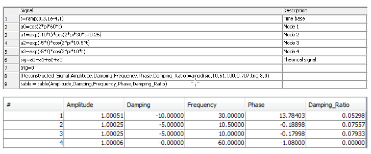
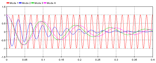
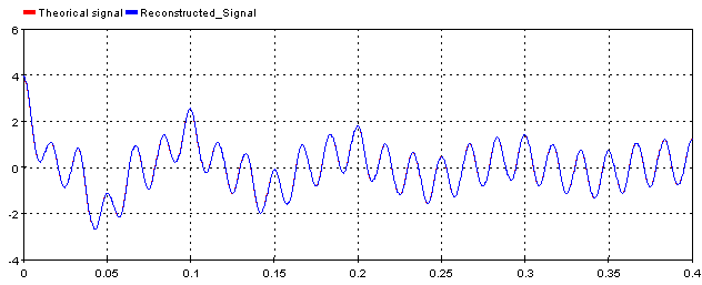
EXAMPLE
For this example, a simple signal is constructed with ScopeView
OPAL-RT TECHNOLOGIES, Inc. | 1751, rue Richardson, bureau 1060 | Montréal, Québec Canada H3K 1G6 | opal-rt.com | +1 514-935-2323