Documentation Home Page ◇ HYPERSIM Home Page
Pour la documentation en FRANÇAIS, utilisez l'outil de traduction de votre navigateur Chrome, Edge ou Safari. Voir un exemple.
Example 2: Using Variables in TestView
- Sylvain Ménard
Example 1 showed how to execute a test sequence that had only hardcoded values. Example 2 will focus on the use of variables to define some parameters in the model. This example will not go into much details regarding the blocks that were used in the first example. It is recommended to do the first example before this one.
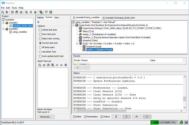
The starting point is the end of the Quick Start tutorial (Link to the Quick Start tutorial). Your TestView should now look like Figure 88.
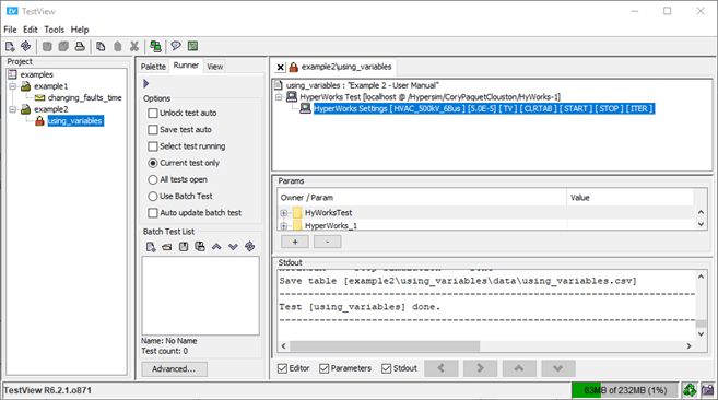
Starting Point: Example 2
This example will modify the resistance of Ld2 in the example HVAC_500kV_6Bus model following the equation
Where ‘index’ is the loop variable and User request will be a pop-up for the user to fill. This equation does not make any physical sense, but it demonstrates quite well how to use several blocks in TestView.
Similarly to example 1, let’s start by making sure that the options Start simulation and Disable Time Events are checked and unchecked, respectively in the HYPERSIM Settings block and let’s add a sleep of 1 second.
The next step is to add an ‘Assign’ block to initialize the variables that we will need for the equation. If the initialization is not done, the test will crash when trying to evaluate the equations for the first time. Fill the Assign block as shown in Figure 89 and press Apply.
The first variable is for the fault current, the second is for the timing of the fault, the third one is for the pop-up window for the user and the fourth is for the result. They are all defined to zero to make sure TestView sees them as numbers, not as strings.
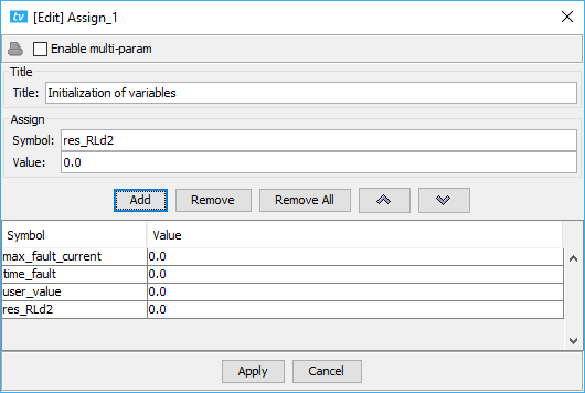
Initialization of Variables
Similarly to the example 1, add a Miscellaneous block to force the General Operation option of the Fault breaker to ‘Enable’ and add a Snapshot block to take a snapshot (you can copy the blocks from the example 1 test and paste it in the example 2 test to save some time. The shortcuts do not work, you need to right-click on the blocks). Let’s add a second parameter, which would be the resistance of Ld2, to be sure it always starts at the same default value.
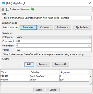
First Miscellaneous Block in Example 2
The next step is to add a loop block for the test, as shown in Figure 90. In this case, we will do four iterations in total, 2 for each part of the equation.
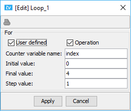
Loop Block in Example 2
Add a Snapshot block in the test to load a snapshot and a breaker block to set the timings for 4 different tests (see example 1). At this point, the test should now look like Figure 91.
Test After Adding the Breaker Block
At this point, it is time to handle the equation itself. The first part is to check if the index is smaller or bigger than 2 to find which of the two halves of the equation to use. In this case, we can use a If/else combo.
Double-click on the if expression in the Palette tab and add the expression in Figure 92. Press Apply to close the window.
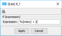
If expression Dialog Box
In Figure 92, the %{} are essential for TestView to understand that it is a variable and not a literal string. TestView would crash if it tried to compare a string to an integer.
Double-click on the else [if(expression)] in the Palette tab to add the else block. Press Apply.
Add a message block under the if expression and under the else expression (you can uncheck the ‘pause’ option in both blocks).
The test should now look like Figure 93. Notice the indentations in Figure 93. If the blocks are not at the right indentations, move them using the arrows in the bottom part of the main TestView window.
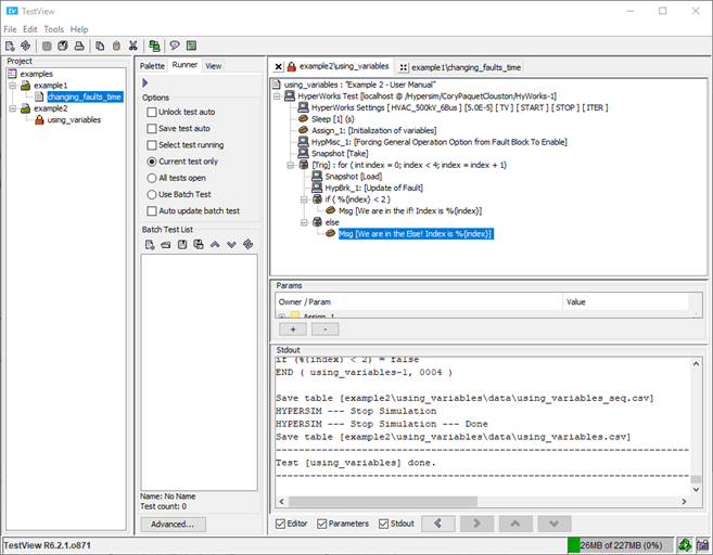
Example 2 Test After Adding the Messages
At this point, it is possible to run the test to see if we made any mistakes. Run it by going in the Runner tab, select the ‘Current test only’ and press play.
In the console, you can see the messages being displayed, as shown in Figure 94.
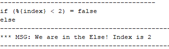
Snippet from the Console Showing that the If and Else is Working
To continue, in the if expression, we need to implement the first half of the equation:
' aria-hidden='true'%3e %3cg transform='translate(167%2c0)'%3e %3cg transform='translate(-11%2c0)'%3e %3cg transform='translate(0%2c-111)'%3e %3cuse xlink:href='%23E1-MJMATHI-52' x='0' y='0'%3e%3c/use%3e %3cg transform='translate(759%2c-150)'%3e %3cuse transform='scale(0.707)' xlink:href='%23E1-MJMATHI-4C' x='0' y='0'%3e%3c/use%3e %3cuse transform='scale(0.707)' xlink:href='%23E1-MJMATHI-64' x='681' y='0'%3e%3c/use%3e %3cuse transform='scale(0.707)' xlink:href='%23E1-MJMAIN-32' x='1205' y='0'%3e%3c/use%3e %3c/g%3e %3cuse xlink:href='%23E1-MJMAIN-3D' x='2343' y='0'%3e%3c/use%3e %3cg transform='translate(3399%2c0)'%3e %3cuse xlink:href='%23E1-MJMAIN-33'%3e%3c/use%3e %3cuse xlink:href='%23E1-MJMAIN-30' x='500' y='0'%3e%3c/use%3e %3cuse xlink:href='%23E1-MJMAIN-30' x='1001' y='0'%3e%3c/use%3e %3c/g%3e %3cuse xlink:href='%23E1-MJMAIN-D7' x='5123' y='0'%3e%3c/use%3e %3cuse xlink:href='%23E1-MJMATHI-55' x='6123' y='0'%3e%3c/use%3e %3cuse xlink:href='%23E1-MJMATHI-73' x='6891' y='0'%3e%3c/use%3e %3cuse xlink:href='%23E1-MJMATHI-65' x='7360' y='0'%3e%3c/use%3e %3cuse xlink:href='%23E1-MJMATHI-72' x='7827' y='0'%3e%3c/use%3e %3cuse xlink:href='%23E1-MJMATHI-72' x='8556' y='0'%3e%3c/use%3e %3cuse xlink:href='%23E1-MJMATHI-65' x='9008' y='0'%3e%3c/use%3e %3cuse xlink:href='%23E1-MJMATHI-71' x='9474' y='0'%3e%3c/use%3e %3cuse xlink:href='%23E1-MJMATHI-75' x='9935' y='0'%3e%3c/use%3e %3cuse xlink:href='%23E1-MJMATHI-65' x='10507' y='0'%3e%3c/use%3e %3cuse xlink:href='%23E1-MJMATHI-73' x='10974' y='0'%3e%3c/use%3e %3cuse xlink:href='%23E1-MJMATHI-74' x='11443' y='0'%3e%3c/use%3e %3cuse xlink:href='%23E1-MJMAIN-2212' x='12027' y='0'%3e%3c/use%3e %3cg transform='translate(12805%2c0)'%3e %3cg transform='translate(342%2c0)'%3e %3crect stroke='none' width='19619' height='60' x='0' y='220'%3e%3c/rect%3e %3cg transform='translate(60%2c725)'%3e %3cuse xlink:href='%23E1-MJMATHI-6D' x='0' y='0'%3e%3c/use%3e %3cuse xlink:href='%23E1-MJMATHI-61' x='878' y='0'%3e%3c/use%3e %3cuse xlink:href='%23E1-MJMATHI-78' x='1408' y='0'%3e%3c/use%3e %3cuse xlink:href='%23E1-MJMATHI-69' x='1980' y='0'%3e%3c/use%3e %3cuse xlink:href='%23E1-MJMATHI-6D' x='2326' y='0'%3e%3c/use%3e %3cuse xlink:href='%23E1-MJMATHI-75' x='3204' y='0'%3e%3c/use%3e %3cuse xlink:href='%23E1-MJMATHI-6D' x='3777' y='0'%3e%3c/use%3e %3cuse xlink:href='%23E1-MJMATHI-66' x='4933' y='0'%3e%3c/use%3e %3cuse xlink:href='%23E1-MJMATHI-61' x='5483' y='0'%3e%3c/use%3e %3cuse xlink:href='%23E1-MJMATHI-75' x='6013' y='0'%3e%3c/use%3e %3cuse xlink:href='%23E1-MJMATHI-6C' x='6585' y='0'%3e%3c/use%3e %3cuse xlink:href='%23E1-MJMATHI-74' x='6884' y='0'%3e%3c/use%3e %3cuse xlink:href='%23E1-MJMATHI-63' x='7523' y='0'%3e%3c/use%3e %3cuse xlink:href='%23E1-MJMATHI-75' x='7957' y='0'%3e%3c/use%3e %3cuse xlink:href='%23E1-MJMATHI-72' x='8529' y='0'%3e%3c/use%3e %3cuse xlink:href='%23E1-MJMATHI-72' x='8981' y='0'%3e%3c/use%3e %3cuse xlink:href='%23E1-MJMATHI-65' x='9432' y='0'%3e%3c/use%3e %3cuse xlink:href='%23E1-MJMATHI-6E' x='9899' y='0'%3e%3c/use%3e %3cuse xlink:href='%23E1-MJMATHI-74' x='10499' y='0'%3e%3c/use%3e %3cuse xlink:href='%23E1-MJMATHI-66' x='11138' y='0'%3e%3c/use%3e %3cuse xlink:href='%23E1-MJMATHI-72' x='11689' y='0'%3e%3c/use%3e %3cuse xlink:href='%23E1-MJMATHI-6F' x='12140' y='0'%3e%3c/use%3e %3cuse xlink:href='%23E1-MJMATHI-6D' x='12626' y='0'%3e%3c/use%3e %3cuse xlink:href='%23E1-MJMATHI-70' x='13782' y='0'%3e%3c/use%3e %3cuse xlink:href='%23E1-MJMATHI-72' x='14286' y='0'%3e%3c/use%3e %3cuse xlink:href='%23E1-MJMATHI-65' x='14737' y='0'%3e%3c/use%3e %3cuse xlink:href='%23E1-MJMATHI-76' x='15204' y='0'%3e%3c/use%3e %3cuse xlink:href='%23E1-MJMATHI-69' x='15689' y='0'%3e%3c/use%3e %3cuse xlink:href='%23E1-MJMATHI-6F' x='16035' y='0'%3e%3c/use%3e %3cuse xlink:href='%23E1-MJMATHI-75' x='16520' y='0'%3e%3c/use%3e %3cuse xlink:href='%23E1-MJMATHI-73' x='17093' y='0'%3e%3c/use%3e %3cuse xlink:href='%23E1-MJMATHI-74' x='17840' y='0'%3e%3c/use%3e %3cuse xlink:href='%23E1-MJMATHI-65' x='18201' y='0'%3e%3c/use%3e %3cuse xlink:href='%23E1-MJMATHI-73' x='18668' y='0'%3e%3c/use%3e %3cuse xlink:href='%23E1-MJMATHI-74' x='19137' y='0'%3e%3c/use%3e %3c/g%3e %3cg transform='translate(9058%2c-687)'%3e %3cuse xlink:href='%23E1-MJMAIN-35'%3e%3c/use%3e %3cuse xlink:href='%23E1-MJMAIN-30' x='500' y='0'%3e%3c/use%3e %3cuse xlink:href='%23E1-MJMAIN-30' x='1001' y='0'%3e%3c/use%3e %3c/g%3e %3c/g%3e %3c/g%3e %3cuse xlink:href='%23E1-MJMATHI-69' x='33165' y='0'%3e%3c/use%3e %3cuse xlink:href='%23E1-MJMATHI-66' x='33510' y='0'%3e%3c/use%3e %3cuse xlink:href='%23E1-MJMATHI-69' x='34339' y='0'%3e%3c/use%3e %3cuse xlink:href='%23E1-MJMATHI-6E' x='34684' y='0'%3e%3c/use%3e %3cuse xlink:href='%23E1-MJMATHI-64' x='35285' y='0'%3e%3c/use%3e %3cuse xlink:href='%23E1-MJMATHI-65' x='35808' y='0'%3e%3c/use%3e %3cuse xlink:href='%23E1-MJMATHI-78' x='36275' y='0'%3e%3c/use%3e %3cuse xlink:href='%23E1-MJMAIN-3C' x='37125' y='0'%3e%3c/use%3e %3cuse xlink:href='%23E1-MJMAIN-32' x='38181' y='0'%3e%3c/use%3e %3c/g%3e %3c/g%3e %3c/g%3e %3c/g%3e %3c/svg%3e)
|
Therefore, we need to ask a value to the user to enter: i.e. to add the Input Value block. To do so, double-click on the Input Value block in the Palette tab and add ‘user_value’ in the field. Press Apply.
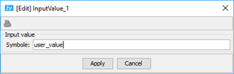
Input Value Dialog Box for Example 2
Notice that no %{} were used to surround the name of the variable. The Input Value block requests for a symbol (i.e. a variable).
You can run again the test sequence. Notice that the pop-up window appears only twice out of four iterations because it is in the if expression (therefore true for index 0 and 1 only).
To continue, we are now at the step of calculating the value of RLd2. For the first iteration, there are no previous test, therefore the ‘maximum fault current from previous test’ will simply be the default value 0.
To calculate RLd2, we have the choice between the Eval block and the Expression block (both will work in this case). Let’s take the Eval block and add the following in the field:
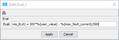
Eval Expression for Index 0 and 1
Notice that res_RLd2 does not have the %{} but the two other variables do. The %{} means “replace that variable by its value”. Therefore, if the expression was
%{res_RLd2} = 300*%{user_value} - %{max_fault_current}/500
TestView would interpret it as (supposing the user enters 1):
0.0 = 300*1 – 0.0/500
Which would throw an exception.
In the else part of the test, let’s add another block to calculate RLd2 for index 2 and 3. Recall that the equation is:
' aria-hidden='true'%3e %3cg transform='translate(167%2c0)'%3e %3cg transform='translate(-11%2c0)'%3e %3cg transform='translate(0%2c-47)'%3e %3cuse xlink:href='%23E1-MJMATHI-52' x='0' y='0'%3e%3c/use%3e %3cg transform='translate(759%2c-150)'%3e %3cuse transform='scale(0.707)' xlink:href='%23E1-MJMATHI-4C' x='0' y='0'%3e%3c/use%3e %3cuse transform='scale(0.707)' xlink:href='%23E1-MJMATHI-64' x='681' y='0'%3e%3c/use%3e %3cuse transform='scale(0.707)' xlink:href='%23E1-MJMAIN-32' x='1205' y='0'%3e%3c/use%3e %3c/g%3e %3cuse xlink:href='%23E1-MJMAIN-3D' x='2343' y='0'%3e%3c/use%3e %3cg transform='translate(3399%2c0)'%3e %3cuse xlink:href='%23E1-MJMAIN-33'%3e%3c/use%3e %3cuse xlink:href='%23E1-MJMAIN-30' x='500' y='0'%3e%3c/use%3e %3cuse xlink:href='%23E1-MJMAIN-30' x='1001' y='0'%3e%3c/use%3e %3c/g%3e %3cuse xlink:href='%23E1-MJMAIN-2212' x='5123' y='0'%3e%3c/use%3e %3cuse xlink:href='%23E1-MJMATHI-61' x='6123' y='0'%3e%3c/use%3e %3cuse xlink:href='%23E1-MJMATHI-63' x='6653' y='0'%3e%3c/use%3e %3cuse xlink:href='%23E1-MJMATHI-74' x='7086' y='0'%3e%3c/use%3e %3cuse xlink:href='%23E1-MJMATHI-69' x='7448' y='0'%3e%3c/use%3e %3cuse xlink:href='%23E1-MJMATHI-76' x='7793' y='0'%3e%3c/use%3e %3cuse xlink:href='%23E1-MJMATHI-61' x='8279' y='0'%3e%3c/use%3e %3cuse xlink:href='%23E1-MJMATHI-74' x='8808' y='0'%3e%3c/use%3e %3cuse xlink:href='%23E1-MJMATHI-69' x='9170' y='0'%3e%3c/use%3e %3cuse xlink:href='%23E1-MJMATHI-6F' x='9515' y='0'%3e%3c/use%3e %3cuse xlink:href='%23E1-MJMATHI-6E' x='10001' y='0'%3e%3c/use%3e %3cuse xlink:href='%23E1-MJMATHI-74' x='10879' y='0'%3e%3c/use%3e %3cuse xlink:href='%23E1-MJMATHI-69' x='11241' y='0'%3e%3c/use%3e %3cuse xlink:href='%23E1-MJMATHI-6D' x='11586' y='0'%3e%3c/use%3e %3cuse xlink:href='%23E1-MJMATHI-65' x='12465' y='0'%3e%3c/use%3e %3cuse xlink:href='%23E1-MJMATHI-6F' x='13209' y='0'%3e%3c/use%3e %3cuse xlink:href='%23E1-MJMATHI-66' x='13695' y='0'%3e%3c/use%3e %3cuse xlink:href='%23E1-MJMATHI-66' x='14523' y='0'%3e%3c/use%3e %3cuse xlink:href='%23E1-MJMATHI-61' x='15073' y='0'%3e%3c/use%3e %3cuse xlink:href='%23E1-MJMATHI-75' x='15603' y='0'%3e%3c/use%3e %3cuse xlink:href='%23E1-MJMATHI-6C' x='16175' y='0'%3e%3c/use%3e %3cuse xlink:href='%23E1-MJMATHI-74' x='16474' y='0'%3e%3c/use%3e %3cuse xlink:href='%23E1-MJMATHI-66' x='17113' y='0'%3e%3c/use%3e %3cuse xlink:href='%23E1-MJMATHI-72' x='17664' y='0'%3e%3c/use%3e %3cuse xlink:href='%23E1-MJMATHI-6F' x='18115' y='0'%3e%3c/use%3e %3cuse xlink:href='%23E1-MJMATHI-6D' x='18601' y='0'%3e%3c/use%3e %3cuse xlink:href='%23E1-MJMATHI-70' x='19757' y='0'%3e%3c/use%3e %3cuse xlink:href='%23E1-MJMATHI-72' x='20260' y='0'%3e%3c/use%3e %3cuse xlink:href='%23E1-MJMATHI-65' x='20712' y='0'%3e%3c/use%3e %3cuse xlink:href='%23E1-MJMATHI-76' x='21178' y='0'%3e%3c/use%3e %3cuse xlink:href='%23E1-MJMATHI-69' x='21664' y='0'%3e%3c/use%3e %3cuse xlink:href='%23E1-MJMATHI-6F' x='22009' y='0'%3e%3c/use%3e %3cuse xlink:href='%23E1-MJMATHI-75' x='22495' y='0'%3e%3c/use%3e %3cuse xlink:href='%23E1-MJMATHI-73' x='23067' y='0'%3e%3c/use%3e %3cuse xlink:href='%23E1-MJMATHI-74' x='23815' y='0'%3e%3c/use%3e %3cuse xlink:href='%23E1-MJMATHI-65' x='24176' y='0'%3e%3c/use%3e %3cuse xlink:href='%23E1-MJMATHI-73' x='24643' y='0'%3e%3c/use%3e %3cuse xlink:href='%23E1-MJMATHI-74' x='25112' y='0'%3e%3c/use%3e %3cuse xlink:href='%23E1-MJMAIN-D7' x='25696' y='0'%3e%3c/use%3e %3cg transform='translate(26697%2c0)'%3e %3cuse xlink:href='%23E1-MJMAIN-31'%3e%3c/use%3e %3cuse xlink:href='%23E1-MJMAIN-30' x='500' y='0'%3e%3c/use%3e %3cuse xlink:href='%23E1-MJMAIN-30' x='1001' y='0'%3e%3c/use%3e %3cuse xlink:href='%23E1-MJMAIN-30' x='1501' y='0'%3e%3c/use%3e %3c/g%3e %3cuse xlink:href='%23E1-MJMATHI-69' x='28976' y='0'%3e%3c/use%3e %3cuse xlink:href='%23E1-MJMATHI-66' x='29322' y='0'%3e%3c/use%3e %3cuse xlink:href='%23E1-MJMATHI-69' x='30150' y='0'%3e%3c/use%3e %3cuse xlink:href='%23E1-MJMATHI-6E' x='30496' y='0'%3e%3c/use%3e %3cuse xlink:href='%23E1-MJMATHI-64' x='31096' y='0'%3e%3c/use%3e %3cuse xlink:href='%23E1-MJMATHI-65' x='31620' y='0'%3e%3c/use%3e %3cuse xlink:href='%23E1-MJMATHI-78' x='32086' y='0'%3e%3c/use%3e %3cuse xlink:href='%23E1-MJMAIN-2265' x='32936' y='0'%3e%3c/use%3e %3cuse xlink:href='%23E1-MJMAIN-32' x='33993' y='0'%3e%3c/use%3e %3c/g%3e %3c/g%3e %3c/g%3e %3c/g%3e %3c/svg%3e)
|
Just for the pedagogical aspect of it, let’s use the Expression block instead of the Eval block for this one.
To add the Expression block to the Test, simply double-click on Expression in the Palette tab and fill the dialog box as presented in Figure 97. Pres Add and then Apply.
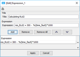
Expression Dialog Box for the Else part of the Script
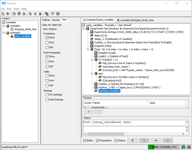
The script should now look like Figure 98.
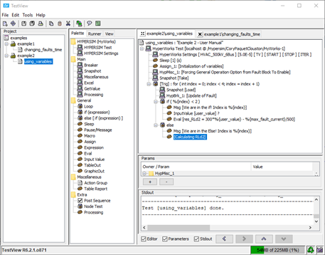
Example 2: Once the Equation is Completely Defined
To make a quick recap of the test up to now: it sets the connections to the model, enables the fault block, takes a snapshot of the steady-state conditions (prior to any fault) then iterates four times. In each iteration, it loads the snapshot, defines the timing for the fault and calculates the value of RLd2 based on the given equation.
What is left to do is to set RLd2 using the result from the equation, to run the tests and to update the variables after each test.
To set RLd2, double-click on Miscellaneous in the Palette tab, and fill the dialog box as presented below. Make sure that you select the Ld2 and R from the dropdown list (and not hardcoding them). Recall that if the lists are empty, it means that there is a connection problem between TestView and HYPERSIM.
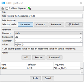
Setting the Resistance of Ld2
The block should be inside the loop but not inside the if or the else expression. Use the arrows to move the block at the right place.
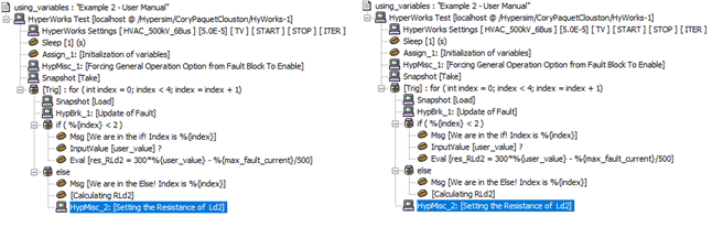
(Left) Block is Not in the Right Place! (Right) Block is in the Right Place
To continue, the next step is to add a processing block (the one in the Main folder of the Palette tab). A shortcut is to copy the one from Example1 and build from it. If you are starting with a new block, don’t forget to create a Signals Key (see Example 1).
We need the maximum current of phase A and the crossing time of the fault. To have those, go in the processing tab of the block and add the following. The functions used are from ScopeView. Please refer to the ScopeView User Manual for more details regarding those.
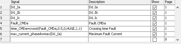
Selected Signals from Processing Tab of Processing Block.
Then, go to the post-processing tab and add the two results to see them. This way, we will see the evolution throughout the four iterations.
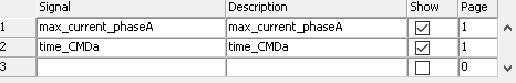
Selected Signals from Post-Processing Tab of the Processing Block
Finally, go back to the general tab and make sure the ‘Show Graphic’ option is set for both the processing and the post-processing option.
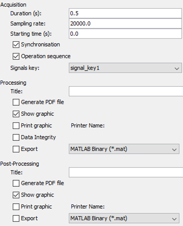
General Tab of the Processing Block
The last block to add is the Expression one to update the variables. Add the block and fill the dialog box as follow:
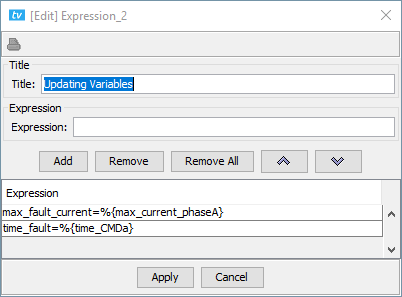
Second Expression Block in Example 2 to Update the Variables
The test should now look like:
Example 2 - Complete Test
To run the test, go in the View tab, check ‘Show’ in the processing and post-processing sections. Go in the runner tab and press play.
WARNING: Do you enter 0 (nor negative) as the user value, it gives a resistance of 0 (or negative), which will make the test crash!
When you run the test, you should see waveforms like in Figure 107. The waveforms depend on the entered value.
Figure 108 shows the waveforms for the post-processing part. There should be four points per graphs because there were four iterations executed. Post-Processing is a way to compare the results from different tests rapidly.
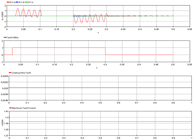
Typical Processing Waveforms for Example 2
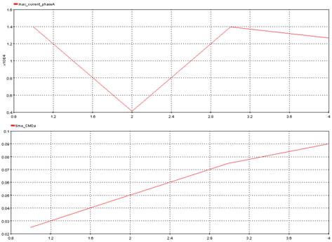
Typical Post-Processing Waveforms for Example 2
Note: The X- Axis in the post-processing graph is not time, it is the test number.
OPAL-RT TECHNOLOGIES, Inc. | 1751, rue Richardson, bureau 1060 | Montréal, Québec Canada H3K 1G6 | opal-rt.com | +1 514-935-2323
Follow OPAL-RT: LinkedIn | Facebook | YouTube | X/Twitter