Documentation Home Page ◇ HYPERSIM Home Page
Pour la documentation en FRANÇAIS, utilisez l'outil de traduction de votre navigateur Chrome, Edge ou Safari. Voir un exemple.
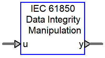
IEC 61850 Data Integrity Manipulation
- Sylvain Ménard
Note:
This block is currently only compatible with the legacy IEC 61850 I/O interface.
The interface introduced in HYPERSIM 2022.1 (documented here) is not yet compatible. Support will be added in subsequent versions.
Introduction
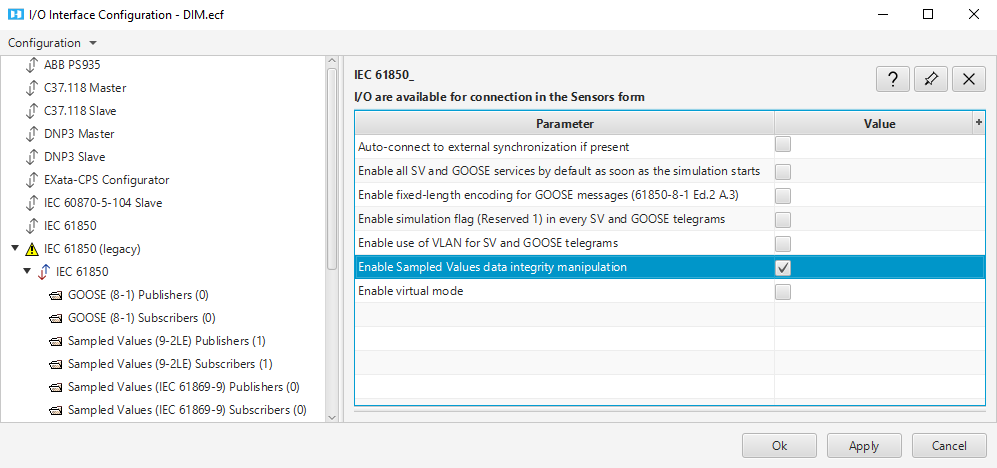
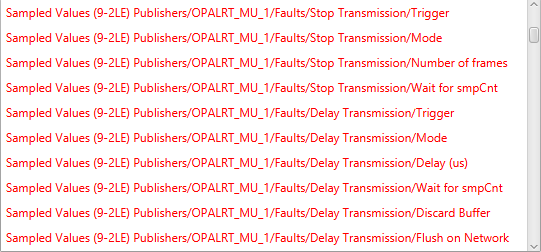
When Sampled Values data integrity manipulation is enabled in I/O Interface Configuration, additional connection points in a new connection group called "Faults" are available to perform error injection into Sampled Values (9-2LE) Publisher messages. The output sensors of the IEC 61850 Data Integrity Manipulation (DIM) component need to be mapped to this new group of connections.
The IEC 61850 Data Integrity Manipulation component is used to perform six different types of manipulations into the Sampled Values Publisher messages, each with a configurable trigger:
| Stop transmission | Simulate the loss of packets on the network by stopping the SV publishing during a certain number of frames. |
| Delay transmission | Simulate an unwanted delay on the network by delaying the frames for a specified amount of time, in microseconds. |
| Duplicate transmission | Simulate a wrong network topology where packets could be sent multiple times by duplicating frames for a certain amount of frames. |
| smpCnt manipulation | Simulate an IED clock reset by manipulating the smpCnt of a given frame. |
| smpSynch manipulation | Simulate a loss of synchronization by manipulating the smpSynch of a stream for a certain number of frames. |
| Quality manipulation | Simulate a change in the IED performance by manipulating the quality of the voltage and current values in a stream. |
Input/output
| Input | u |
| CLK_Ref_sec | epoch second of the external clock. |
| CLK_is_sync | a Boolean signal showing the synchronization state of the external clock. |
| CTRL_POW | connect to the "SyncOut" sensor output of the POW component, in order to trigger the manipulation. |
| Output | y (sensors to be mapped to IEC 61850 driver) |
Parameters
General Tab
The General tab lets the user enable and associate to a Merging Unit and choose which manipulation to enable. Each component can be linked to two SV Publisher streams.
Settings for each manipulation can be selected in their individual tabs (if enabled in the General tab).

Loss Tab
The Loss manipulation simulates the loss of packets on the network by stopping the SV publishing during a certain amount of frames. If monitored, the stream will appear as it loses n packets of data.

- Trigger on next smpCnt value: select to enable and specify the value at which to begin the manipulation (rather than at t=T).
- Number of lost SV: specify the number of packets that should be lost.
Duplication Tab
The Duplication manipulation duplicates a stream the number of times specified and for a specific number of packets.

- Trigger on next smpCnt value: select to enable and specify the value at which to begin the manipulation (rather than at t=T).
- Number n of affected SV: specify the number of SV that will be affected.
- Number d of duplicated frames: specify the number of frames to duplicate.
smpCnt Tab
The smpCnt manipulation changes the smpCnt value according to user settings. It then simulates a new synchronization from the Merging Unit without affecting the current smpSynch value.

- Trigger on next smpCnt value: select to enable then specify whether the effect should be applied at a specific smpCnt value.
- New smpCnt value: specify the new smpCnt value. If monitored, the stream will appear as it jumps from its normal to the new smpCnt value.
Delay Tab
The Delay manipulation delays a stream D μs by storing the frames in a buffer. If monitored, the stream will appear delayed.

- Trigger on next smpCnt value: select to enable and specify whether the effect should be applied at the specified value (rather than t=T).
- Delay D applied to the stream [μs]: Specify the length of the delay.
- Delay n before recovery: specify the delay, in seconds, before the stream recovers from the delay.
- Discard or release the buffer on recovery: select Release (default) or Discard. Recovery can be made by releasing the buffer’s content on the network or by discarding it, as shown.
smpSynch Tab
The smpSynch manipulation changes the smpSynch value according to user settings. It then simulates a synchronization loss, change or gain from the Merging Unit.

- Trigger on next smpCnt value: select to enable and specify the value at which to begin the manipulation (rather than at t=T).
- Number n of affected SV: specify the number of SV packets that will be affected.
- New smSynch value: specify the new smpSynch value. If monitored, the stream will appear as it goes from its current smpSynch to the new one.
Quality Bits Tab
The Quality Bits manipulation changes the quality bits values according to user settings.

- Trigger on next smpCnt value: select to enable and specify the value at which to begin the manipulation (rather than at t=T).
- Number n of affected SV: specify the number of SV packets that will be affected.
- Current ph A, ... , Voltage ph N: specify the quality bit for each current and voltage value in the SV stream.
Sensors
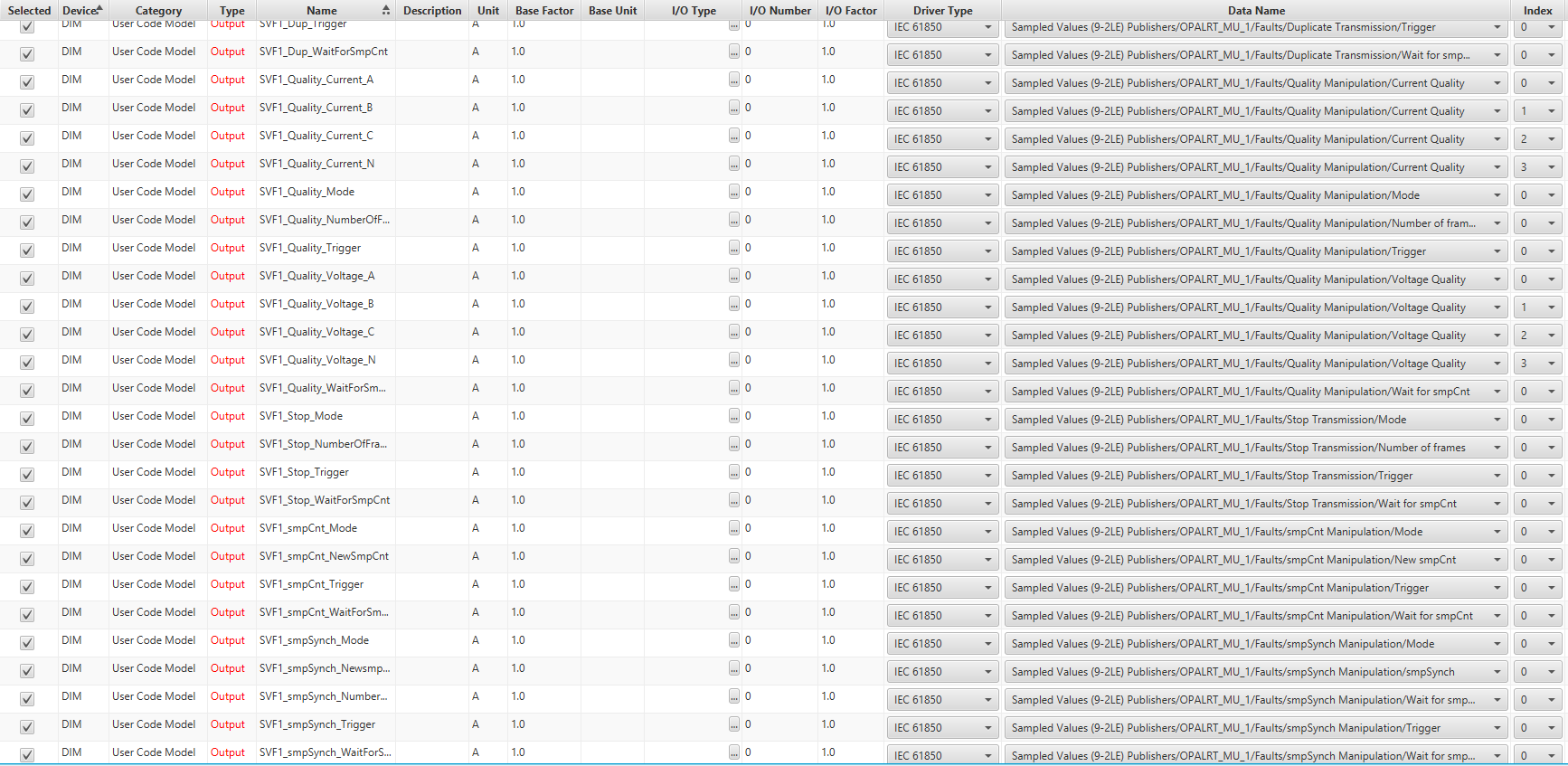
For DIM to be functional, you must map the connection points from IEC 61850 driver to the ones found in the sensors form for DIM. More connection details can be found here.
An example is shown below:
When an external clock (Oregano Syn1588 PCIe) is used to synchronize the data streams, the user has to manually map the clock sensors, 'Auto-connect to external synchronization if present' option is overwritten.
The inputs are mapped to the Synchronization data points and the outputs are mapped to the IEC 61850 Clock data points:

Notes
- There can be multiple DIM components in the same model.
- Different types of data manipulation can be enabled at the same time.
- Each Merging Unit in the DIM can only be mapped to one SV stream.
OPAL-RT TECHNOLOGIES, Inc. | 1751, rue Richardson, bureau 1060 | Montréal, Québec Canada H3K 1G6 | opal-rt.com | +1 514-935-2323
Follow OPAL-RT: LinkedIn | Facebook | YouTube | X/Twitter