Documentation Home Page ◇ Hardware Home Page
Pour la documentation en FRANÇAIS, utilisez l'outil de traduction de votre navigateur Chrome, Edge ou Safari. Voir un exemple.
OP5707-IO IO Connectors
DB37F Connectors
Analog I/O Modules
Each pair of I/O modules (A and B) is linked to four (4) female DB37 connectors (I/Os) on the back of the chassis:
The first two connectors (left to right) represent channels from Group B, which are linked to the conditioned channels from the rear I/O module.
The last two connectors (left to right) represent channels from Group A, which are linked to the conditioned channels from the front I/O module.
- If the front I/O module (A) is an analog module (DAC or ADC):
- The 16 channels are on connector A-P1
- Connector A-P2 does not carry any signals.
- If the back I/O module (B) is an analog module (DAC or ADC):
- The 16 channels are on connector B-P1.
- Connector B-P2 does not carry any signals.
Digital I/O Modules
Each pair of I/O modules (A and B) is linked to four (4) female DB37 connectors (I/Os) on the back of the chassis:
The first two connectors (left to right) represent channels from Group B, which are linked to the conditioned channels from the rear I/O module.
The last two connectors (left to right) represent channels from Group A, which are linked to the conditioned channels from the front I/O module.
If the front I/O module (A) is a digital module (Din or Dout):
- The first 16 channels (00 to 15) are on the connector A-P1.
- The next 16 channels (16 to 31) are on the connector A-P2.
- If the back I/O module (B) is a digital module (Din or Dout):
- The first 16 channels (00 to 15) are on the connector B-P1
- The next 16 channels (16 to 31) are on the connector B-P2
All signals are represented by a positive-negative pair that are always available on the connector pins, for example: for channel 08 : (08+, -08)
Positive/Negative Signals Connection
- For a single-ended output, the negative conductor is connected to Ground
- For a differential output, the positive and negative signals are on the connector
- For a differential input, the connection must be between the positive/negative pair
- If the input is single-ended, user ground must be connected to the negative side of the pair
RJ45 Connectors
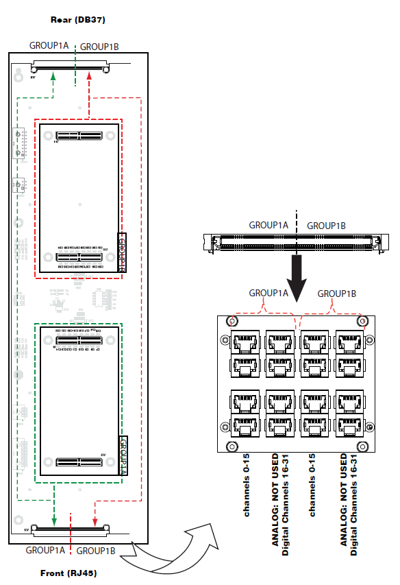
Each RJ45 monitoring panel on the front of the OP5707-IO I/O expansion unit connects to front and back I/O modules.
The following images illustrate how the I/O modules are linked to the connectors.
OP5707-IO I/O expansion unit - Rear (DB37)
RJ45 Channel Assignments
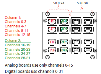
Each I/O module is assigned two columns of RJ45 connectors.
Each column represents a series of channels, divided into 4 channels per jack, as shown in the figure below.
OPAL-RT TECHNOLOGIES, Inc. | 1751, rue Richardson, bureau 1060 | Montréal, Québec Canada H3K 1G6 | opal-rt.com | +1 514-935-2323
Follow OPAL-RT: LinkedIn | Facebook | YouTube | X/Twitter
.png?version=1&modificationDate=1678586815110&cacheVersion=1&api=v2&width=400&height=560)
.png?version=1&modificationDate=1678586814708&cacheVersion=1&api=v2&width=400&height=616)

