Documentation Home Page ◇ Hardware Home Page
Pour la documentation en FRANÇAIS, utilisez l'outil de traduction de votre navigateur Chrome, Edge ou Safari. Voir un exemple.
OP5600V2 IO Connectors
DB37F Connections
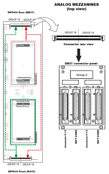
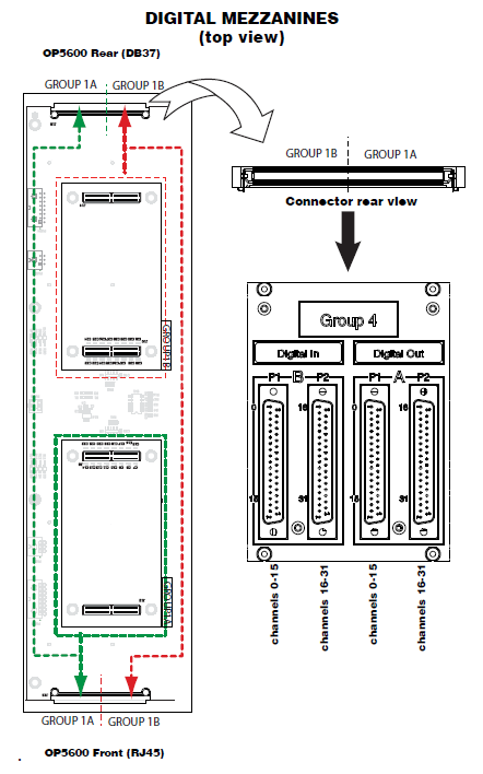
Each pair of mezzanines (A & B) is linked to four female DB37 connectors (I/Os) on the back of the chassis:
The first two connectors (left to right) represent channels from Group B, which are linked to the conditioned channels from the back mezzanine. The last two connectors (left to right) represent channels from Group A, which are linked to the conditioned channels from the front mezzanine.
Analog Mezzanines
If the front mezzanine is an analog module (DAC or ADC), the 16 channels are on connector A and connector B does not carry any signals.
If the back mezzanine is an analog module (DAC or ADC), the 16 channels are on connector C. Connector D does not carry any signals.
Digital Mezzanines
If the front mezzanine is a digital module (Din or Dout), the first 16 channels (00 to 15) are on the first connector and the next 16 channels (16 to 31) are on the second connector.
If the back mezzanine is a digital module (Din or Dout), the first 16 channels (00 to 15) are on the first connector and the next 16 channels (16 to 31) are on the second connector.
All signals are represented by a positive-negative pair that are always available on the connector pins, for example: for channel 08 : (08+, -08)
Positive/negative channel connections
- For a single-ended output, the negative conductor is connected to Ground
- For a differential output, the positive and negative signals are on the connector
- For a differential input, the connection must be between the positive/negative pair
- If the input is single-ended, user’s ground must be connected to the negative side of the pair
RJ45 Connectors
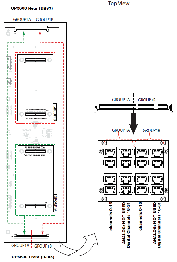
Each RJ45 monitoring panel on the front of the OP5600 simulator connects to a group of two mezzanines. The following images illustrate how the mezzanines are linked to the connectors.
RJ45 Channel Assignments
Each mezzanine is assigned two columns of RJ45 connectors. Each column represents a series of channels, divided into 4 channels per jack, as shown in the following figure.
OPAL-RT TECHNOLOGIES, Inc. | 1751, rue Richardson, bureau 1060 | Montréal, Québec Canada H3K 1G6 | opal-rt.com | +1 514-935-2323
Follow OPAL-RT: LinkedIn | Facebook | YouTube | X/Twitter


