Documentation Home Page ◇ Hardware Home Page
Pour la documentation en FRANÇAIS, utilisez l'outil de traduction de votre navigateur Chrome, Edge ou Safari. Voir un exemple.
OP4200 Testing Signals Using the Loopback Kit
Note: The following procedure is only used for test purposes when no external source is available.
System signals are tested using the loopback kit included in the starter kit. The connection is made easy with a custom flat cable that matches OPAL-RT standard DB37 pin assignments.
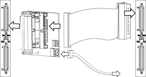
Signals are tested using the loopback kit by connecting the output cassette to the input cassette. If the input reads each output signal, the unit is functioning properly and is ready to be put into service.
From left to right:
Output cassette, loopback board, To external source, Input cassette.
- Connect one end of the flat cable to the loopback board
- Connect the loopback board to the OP4200 DB37 output cassette
- Connect the other end (DB37 connector) of the flat cable to the OP4200 DB37 input cassette
- When this kit is used to test digital signals, connect the Vuser* using the cable provided in the starter kit (P/N 113-0927) from the loopback board (connector end) to an external source (wire end).
* For more information about the use of Vuser and Vrtn pleaser refer to this article in the OPAL-RT knowledge base : How to power the different DB37 boards for digital outputs.
OPAL-RT TECHNOLOGIES, Inc. | 1751, rue Richardson, bureau 1060 | Montréal, Québec Canada H3K 1G6 | opal-rt.com | +1 514-935-2323
Follow OPAL-RT: LinkedIn | Facebook | YouTube | X/Twitter
