Documentation Home Page ◇ Hardware Home Page
Pour la documentation en FRANÇAIS, utilisez l'outil de traduction de votre navigateur Chrome, Edge ou Safari. Voir un exemple.
Activity and status LEDs
- Sylvain Ménard
On the front plate of each module, three LEDS labelled Power, Activity and Fault, give information about the module status :
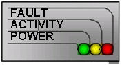
| LED color | LED Purpose | Description |
|---|---|---|
| Green | Power | This LED indicates that the digital power supplies (5V or 3.3V) of the card are within the validity range. This LED is not software controlled. |
| Yellow | Activity | Driven by the FPGA, this LED indicates the model status :
Moreover, when the red fault LED is ON, the yellow Activity LED indicates error codes related to the FPGA of the module :
|
| Red | Error | Driven by the FPGA, this LED indicates that a fault related to this module has been detected. In case an error is detected, the FPGA program attempts to protect the hardware, for example by disabling the faulty channels, and sets the fault LED to ON, informing the operator of this abnormal condition. In addition, the error condition is reported to the simulation model and displayed in the module's run-time panel. The fault conditions can come from hardware or software malfunction. Typical hardware faults are, but a not limited to :
Typical software faults are, but are not limited to :
Faults that can be transient, like over current, over voltage, etc., can be acknowledged from the module's run-time panel. Upon acknowledgment of the fault, the FPGA re-enables the hardware, and re-checks for the fault condition. If the fault condition is no longer detected, the red LED is cleared. If the fault condition is still present, the red LED is set to ON again. The red LED of some modules (POM, PDL, SM) lights on during a few seconds when the system is powered up. This does not signal a fault of these modules. |
OPAL-RT TECHNOLOGIES, Inc. | 1751, rue Richardson, bureau 1060 | Montréal, Québec Canada H3K 1G6 | opal-rt.com | +1 514-935-2323
Follow OPAL-RT: LinkedIn | Facebook | YouTube | X/Twitter