Documentation Home Page ◇ HYPERSIM Home Page
Pour la documentation en FRANÇAIS, utilisez l'outil de traduction de votre navigateur Chrome, Edge ou Safari. Voir un exemple.
Signal Generator | Configuration
- Sylvain Ménard
- Victoria Bruny
Accessing the I/O Interface Configuration
The Signal Generator protocol can be configured in the I/O Interface Configuration tool that is opened from the HYPERSIM ribbon.
- For more information on the general use of the I/O Interface Configuration, see here.
- For more information on the configuration of the I/O Connection, see here.
General Configuration
The Signal Generator driver is configured through several pages. The first page contains generic configuration.
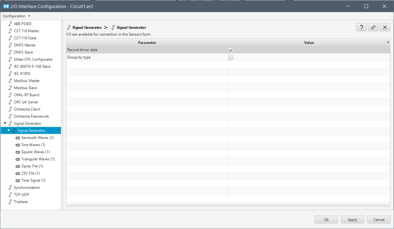
| Record driver data | Select this option to record all inputs/outputs of the signal generator driver. |
| Group by type | Select this option to group recorded data by signal type. |
- Any number of each signal type can be added.
- Signal Waves (except for Time Signal) have almost the same type and number of input parameters: Frequency, Amplitude, Phase, and Offset.
- The square wave has an additional parameter: Duty Cycle.
- These parameters can be edited while the simulation is running, but connections must be made between the driver data point and the model data point to make it work. All signals can be displayed in ScopeView.
Supported Signals
Sawtooth Waves
To add a signal, click any of the Add 1 item buttons, depending on if you want to add it Above or Below the selected Signal.
The arrow next to each button provides more options (duplicate signals and/or add multiple signals simultaneously).
You can remove one or several signals, or reorder them by using the arrow buttons.
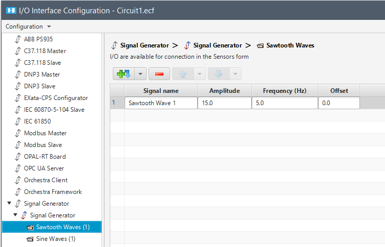
| Signal Name | Name of the signal. |
|---|---|
| Amplitude | Amplitude of the signal. |
| Frequency (Hz) | Frequency of the signal in Hertz. |
| Offset |
Sine Waves
To add a signal, click any of the Add 1 item buttons, depending on if you want to add it Above or Below the selected Signal.
The arrow next to each button provides more options (duplicate signals and/or add multiple signals simultaneously).
You can remove one or several signals, or reorder them, by using the arrow buttons.
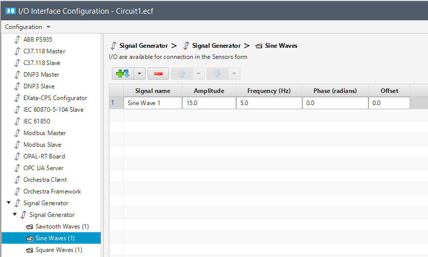
| Signal Name | Name of the signal. |
|---|---|
| Amplitude | Amplitude of the signal. |
| Frequency (Hz) | Frequency of the signal in Hertz. |
| Phase (radians) | Phase of the signal in radians |
| Offset |
Square Waves
To add a signal, click any of the Add 1 item buttons, depending on if you want to add it Above or Below the selected Signal.
The arrow next to each button provides more options (duplicate signals and/or add multiple signals simultaneously).
You can remove one or several signals, or reorder them, by using the arrow buttons.
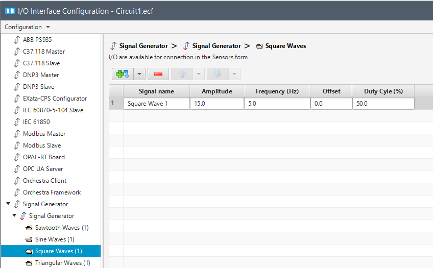
| Signal Name | The name of the signal. |
|---|---|
| Amplitude | Amplitude of the signal. |
| Frequency (Hz) | Frequency of the signal in Hertz. |
| Offset | |
| Duty Cycle (%) | It determines the amount of time the square signal is active. |
Triangular Waves
To add a signal, click any of the Add 1 item buttons, depending on if you want to add it Above or Below the selected Signal.
The arrow next to each button provides more options (duplicate signals and/or add multiple signals simultaneously).
You can remove one or several signals, or reorder them, by using the arrow buttons.
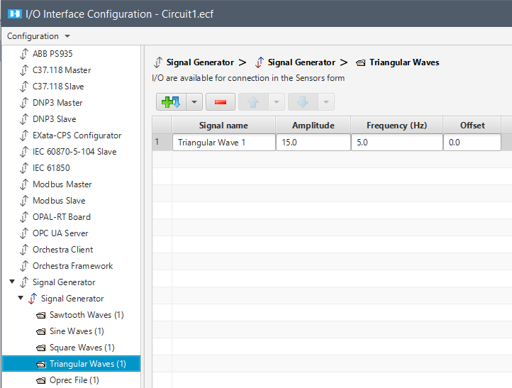
| Signal Name | The name of the signal. |
|---|---|
| Amplitude | Amplitude of the signal. |
| Frequency (Hz) | Frequency of the signal in Hertz. |
| Offset |
Oprec Files
To input an .oprec file in HYPERSIM, you must create it via the datalogger. See Datalogger section for more information on the generation.
To add a file, click any of the Add 1 item buttons, depending on if you want to add it Above or Below the selected File.
The arrow next to each button provides more options (duplicate files and/or add multiple files simultaneously).
You can remove one or several files, or reorder them, by using the arrow buttons.
To configure the I/O interface, paste the absolute path of your .oprec file, and select Repeat mode if needed.
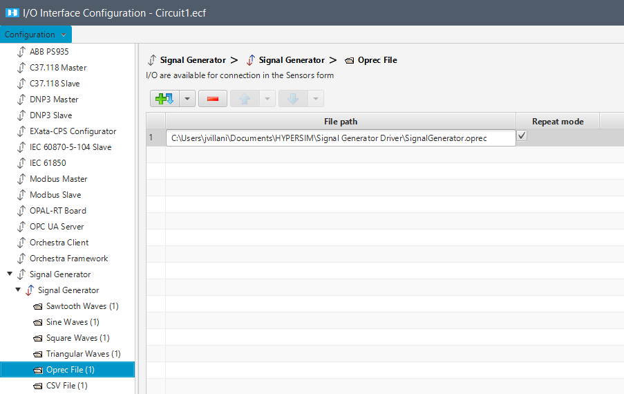
| File Path | Absolute path to your .oprec file. it must be in the same directory as your model.ecf file. |
|---|---|
| Repeat mode | Allows you to repeat the value you set up in your .oprec file while the simulation is running. |
CSV Files
To input a .csv file in HYPERSIM, you must create a file with the following formatting and make sure you saved the .csv file at the same location as your model (.ecf)
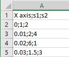
CSV supported format
The only supported separator is the semi-colon (;). It is used to separate header entries but also values.
The first line (as almost CSV files) corresponds to the header. It is made of the simulation timestamp (X axis) followed by the names of the signals.
Each following line corresponds to a computation step. The first value must be the simulation timestamp (in seconds), followed by the signal values in the same order as defined in the header.
In the example below, we are using two inputs (s1 and s2) in addition to the simulation timestamp. The time is going from 0 to 0.03 with an increment of 0.01.
To add a file, click any of the Add 1 item buttons, depending on if you want to add it Above or Below the selected File.
The arrow next to each button provides more options (duplicate files and/or add multiple files simultaneously).
You can remove one or several files, or reorder them, by using the arrow buttons.
To configure the I/O interface, paste the absolute path of your .csv file, and select Repeat mode if needed.
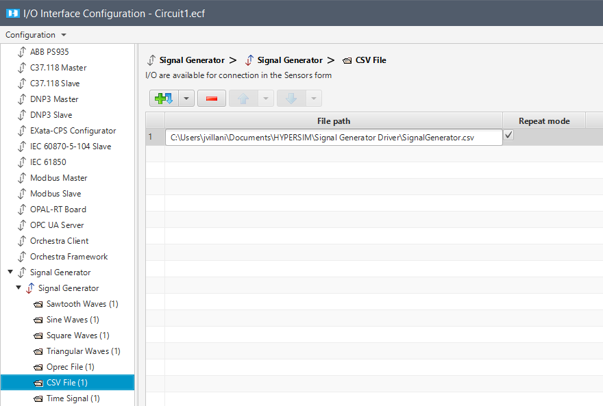
| File Path | Absolute path to your .csv file. it must be in the same directory as your model.ecf file. |
|---|---|
| Repeat mode | Allows you to repeat the value you set up in your .csv file while the simulation is running. When selected, the simulation timestamp provided by the file is not used. |
Time Signal
To add a signal, click any of the Add 1 item buttons, depending on if you want to add it Above or Below the selected Signal.
The arrow next to each button provides more options (duplicate signals and/or add multiple signals simultaneously).
You can remove one or several signals, or reorder them, by using the arrow buttons.
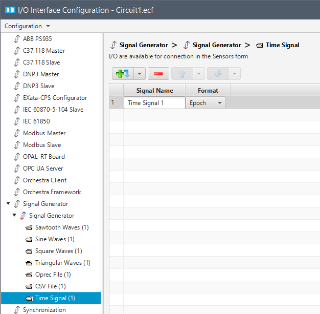
This type of signal is used to replace...:
| Signal Name | Name of the signal. |
|---|---|
| Format | Format of the signal. Only Epoch time is supported. Epoch date and time from which system time is measured. Number of seconds elapsed since 00.00.00 January 1st, 1970. On a Linux machine, it can be obtained using the following command: date +%s |
Monitoring the Results in ScopeView
Since ScopeView monitors the simulation regardless of where the simulation actually is, the starting value might differ depending on when you click on play in acquisition.
Further information on ScopeView available at this link.
OPAL-RT TECHNOLOGIES, Inc. | 1751, rue Richardson, bureau 1060 | Montréal, Québec Canada H3K 1G6 | opal-rt.com | +1 514-935-2323
Follow OPAL-RT: LinkedIn | Facebook | YouTube | X/Twitter