Documentation Home Page ◇ Specialized Solutions Home Page
Pour la documentation en FRANÇAIS, utilisez l'outil de traduction de votre navigateur Chrome, Edge ou Safari. Voir un exemple.
OP1261 Measurement Box
- Sylvain Ménard
The OP1261 is a connection hub for all OP1210 and the OP1260 protection, therefore it is the ideal place to centralize AC and DC control measurements. It allows users to implement these variables in their control schemes to regulates power flow between the MMC and the AC or DC grid. It also allows the user control to synchronize on the AC grid.
The following signals can be measured through this unit:
- AC 3-phase voltages (L1 to neutral, L2 to neutral and L3 to neutral)
- DC voltage
- AC 3-phase current
- DC current
The OP1261 measurement box also provides the auxiliary 48V power supply to the OP1210 units. The MMC topology interconnections (grid, sub-modules, inductors) are made through the OP1261.
User Interface
Front Interface

- DC measurement connector (banana jack): allows users to monitor DC voltage on external equipment (oscilloscope or multimeter). Use only high voltage differential probes.
- AC measurement connector (banana jack): allows users to monitor AC voltage on external equipment (oscilloscope or multimeter). Use only high voltage differential probes.
- Power switch: provides power to measurement circuits on internal board (5511) and controls auxilliary power to OP1210 units
Rear Interface
OP1261 Standard Configuration
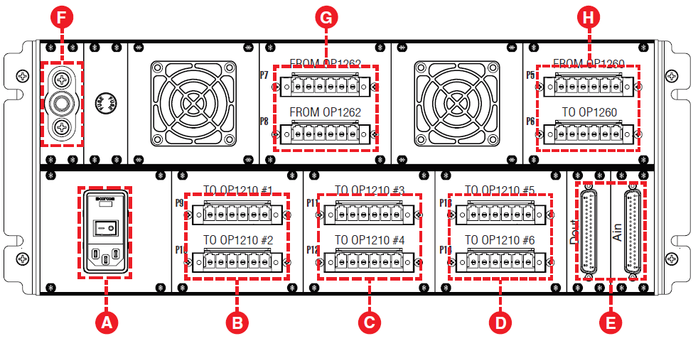
- Auxiliary power connector and switch.
- Phoenix terminal connectors: cables connecting output to OP1210 #1 and #2
- Phoenix terminal connectors: cables connecting output to OP1210 #3 and #4
- Phoenix terminal connectors: cables connecting output to OP1210 #5 and #6
- DB37 connectors: Dout carries digital signals from the OP4510 (which controls relays), Ain carries measurement signals to the OP4510 (see “Pin Assignments” for details).
- Grounding connection: connects ground cable from OP1261 to rack grounding bar
- Phoenix terminal connectors: cable interconnection with OP1262 Inductance Box
- Phoenix terminal connectors: P5 connects cable from P4 on OP1260 power output (see Figure 13)
Pin Assignments
The following tables provide the generic pin assignments for the OP1261’s DB37 and DB9 connectors. More detailed information, tailored to specific firmware, can be found in the Integration documents provided with your order.
DB37 Pin Assignments
DB37 pin | Channel pin assignment | DB37 | Channel pin assignment | |
|---|---|---|---|---|
1 | + 00 | 20 | - 00 |
|
2 | + 01 | 21 | - 01 | |
3 | + 02 | 22 | - 02 | |
4 | + 03 | 23 | - 03 | |
5 | + 04 | 24 | - 04 | |
6 | + 05 | 25 | - 05 | |
7 | + 06 | 26 | - 06 | |
7 | + 07 | 27 | - 07 | |
9 | + 08 | 28 | - 08 | |
10 | + 09 | 29 | - 09 | |
11 | + 10 | 30 | - 10 | |
12 | + 11 | 31 | - 11 | |
13 | + 12 | 32 | - 12 | |
14 | + 13 | 33 | - 13 | |
15 | + 14 | 34 | - 14 | |
16 | + 15 | 35 | - 15 | |
17 | +12V* | 36 | DGND | |
18 | Vuser** | 37 | Vrtn | |
19 |

* Non-isolated, limited to 400mA
** For more information about the use of Vuser and Vrtn pleaser refer to this article in the OPAL-RT knowledge base : How to power the different DB37 boards for digital outputs.
OPAL-RT TECHNOLOGIES, Inc. | 1751, rue Richardson, bureau 1060 | Montréal, Québec Canada H3K 1G6 | opal-rt.com | +1 514-935-2323
Follow OPAL-RT: LinkedIn | Facebook | YouTube | X/Twitter