Documentation Home Page ◇ HYPERSIM Home Page
Pour la documentation en FRANÇAIS, utilisez l'outil de traduction de votre navigateur Chrome, Edge ou Safari. Voir un exemple.
User-Coded Model (UCM)
- Sylvain Ménard
- Maxime Josse
On this page:
In this section:
- UCM | Line Model
- UCM | Substation Modeling
- UCM | Switches
- UCM | Preparation, Simulation & Parallel Tasks
- UCM | Definition File
- UCM | Composition
- UCM | Iteration
- UCM | Editing
- UCM | Builder
- UCM | Protecting Code and Intellectual Property (IP)
User-Coded Model: Introduction
- The User Coded Model (UCM) is a HYPERSIM utility allowing users to build custom models that are not otherwise buildable using existing models. As its name implies, a UCM is coded by users, using the C language, and according to HYPERSIM rules.
- The UCM helps users to build models composed of power and control parts. The advantage of using the UCM is that its power part is solved simultaneously with other power components.
- The UCM’s admittance is added to the admittance of the whole substation, and all node voltages are solved together in the same step. This gives greater numerical stability than if the user’s model power part is represented as controlled sources, which imply one-step delay.
- Because the UCM’s power part is solved together with other power elements, users must follow the same procedure used in HYPERSIM algorithm to solve node voltages. The control part is simply a relationship between inputs and outputs and is simpler to model.
This document is intended as both a UCM user manual and tutorial. It contains the following sections:
| Solution method in HYPERSIM | How HYPERSIM models power elements, handles non-linearity, solves node equations, and organizes parallel tasks. This helps understand the procedure of building a UCM. |
|---|---|
| User-Coded Model | Description of the UCM and the procedure to build and use UCMs. |
| Progressive practice with UCM | Series of examples to instruct users on and provide practice with UCMs. |
The HYPERSIM solution method is based on the traditional EMTP technique. Using the trapezoidal rule for integration, the EMTP converts most power system lump components into resistors and current sources and, finally, solves for node voltages.
- HYPERSIM takes advantage of transmission lines to separate the whole power system into parallel tasks and simulate them in parallel computers. This chapter first describes the line model and shows that events happening at one end of the line affect the other end only after a transmission delay. Different types of branches are analyzed to show that they can be represented as resistor-source equivalents.
- The simulation of a network is therefore summarized by the modeling of lines and the solution of node equations formed by resistors and current sources to find the node voltages. Non-linear elements and switches affect the model's behavior during the simulation and require HYPERSIM to recalculate during the simulation.
- HYPERSIM also simulates control systems by representing them as relationships of outputs to inputs.
- HYPERSIM is composed of a user interface and a simulation program. The interface is not only a graphical interface but also analyses the network, calculates models and generates the code necessary for the simulation. Most of the simulation preparation is done in the interface to optimize simulation speed. The simulation program can run either in real-time on parallel computers or non-real-time on workstations.
HYPERSIM provides a large library of models for power elements and control blocks. Users can also build models graphically using subsystems that contain HYPERSIM elements and blocks.
The User Coded Model (UCM) is provided to model cases and scenarios that could not otherwise be simulated with the available HYPERSIM models and blocks.
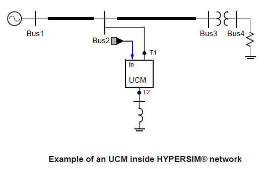
Graphically, as shown in the example, a UCM looks like every other HYPERSIM model. It has power connectors (T1, T2 in the example) to connect to the network through bus bars, control connectors (In in the example) to connect to measurement and control signals. The behavior of the UCM is completely defined by the user, using their own code written in C or C++. HYPERSIM supports C89 standard mathematical functions in the UCM (but does not support C11, C90 or C99). For examples and more detailed information on C mathematical functions, consult the following reference: http://en.cppreference.com/w/c/numeric/math
The admittance matrix has a certain degree of sparsity, indicated by the matrix Yfill:
The dimension of all these matrices is equal the total number of external and internal nodes. The UCM can have current sources, as well as historic currents, injected to internal/external nodes.
The code provided by the user calculates the admittance matrix, current sources, historic currents and performs all desired control functions.
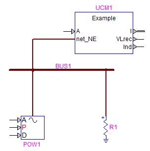
Control input A fixes the amplitude of the 3 phase sine-wave voltage source, which has an output resistor Rs. The source resistor is then connected with a non-linear inductor L through an internal node NI. The other end of the inductor is connected to an external node NE to be connected to a HYPERSIM network (an internal node cannot be connected to a HYPERSIM network). The three-phase currents of the inductor IL_a, IL_b, IL_c are output to a multiplex port IL for monitoring purposes. The three-phase voltages across the inductor are rectified and sent to output port VLrec.
The non-linear inductor has its value L depending on the rectified voltage VLrec as shown also in. The output Ind indicate the actual step number on the non-linear curve.
Using a UCM in a HYPERSIM diagram
- Launch HYPERSIM using its shortcut
- Create a new model or open an existing one
- Click the HYPERSIM tab to display the HYPERSIM ribbon
- In the Import section, click UCM/Import UCM
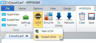
Importing UCM
- Select the .def file to import using the file explorer and click Open
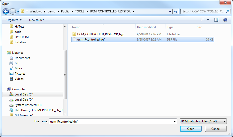
Selecting the .def File
- The selected UCM appears in the diagram with its power connectors representing external nodes and control I/Os. Internal nodes are not visible
- The UCM can then be connected similar to any other component/model within a HYPERSIM diagram. The Example UCM with a simple network is shown in x-y.
- Double-clicking a UCM opens its Parameters window, which shows the list of all input parameters. Users can change them, in the same way as with any other model in HYPERSIM.
- Right-click a UCM and click Edit Sensors to bring up the UCM’s sensor list and choose those to be plotted in ScopeView.
Sensors available are:
- Current sources
- Historic currents
- Controls IOs.
Management of UCM Library
A UCM can be added to the HYPERSIM library and then becomes accessible through the HYPERSIM component palette, as with any other model.
The procedure to put a UCM into the HYPERSIM library is the same as with a sub-system, a hyperlinked model or a user code block (UCB).
Using a Windows Library in a UCM
- Users can use different types of libraries using gcc supplied by HYPERSIM.
- Note that {HYPERSIM_DIR} is the HYPERSIM installation directory. By default, it should resemble: C:\OPAL-RT\HYPERSIM\hypersim_R6.0.XX.oYYY
- Note that {TOOLS_MINGW} is the HYPERSIM tools installation directory. By default, it should be something like C:\OPAL-RT\HYPERSIM\tools\MinGW\X.X.X
- Library paths are absolute. Each time the library file is changed in the directory (it is moved or the simulation is used on another computer), the paths in .def file must be updated.
Generating a .dll Library
- Open a command line window and go to the directory where your C code is.
Generate the .o file by replacing the filename with the correct one.
{TOOLS_MINGW}\bin\gcc -c test.c -o test.oGenerate the dll file using the following command. By convention, the DLL file should be lib{name of your lib}.dll. In this case library name is test. The .lib file name is arbitrary.
{TOOLS_MINGW}\bin\gcc -shared -o libtest.dll test.o -Wl,--out-implib, libtest_dll.libAdd the path of library to the UCM. Open the def file and fill in the following line:
UCM_SIMULATION_LIBRARIES_WINDOWS = -L{Path to your lib} –l{name of your lib} *without extension* the path is entered using / instead of \.Example where {Path to your lib} = C:/Users/joffreynadeau/test_code/ and {name of your lib} =libtest.dll:
UCM_SIMULATION_LIBRARIES_WINDOWS =-LC:/Users/joffreynadeau/test_code/ -ltest
Then, in the Definitions section, add the function you want to import.
In this case, the function is myFunc:
3-1-577
/* 9.3.2 -- Definitions *
#ifdef __cplusplus
extern "C" {
#endif
int myFunc(int);
#ifdef __cplusplus
}
#endif
Now you can use your functions in the UCM.
Example :
%% BEGIN AFTER VOLTAGE CALCULATION -- Enter code ->...
out12 = myFunc(in12);
Generating a .lib
- Open a command line window and go to the directory where your C code is.
- Generate the .o file by replacing the filename with the correct one:
{TOOLS_MINGW}\bin\gcc -c test.c -o test.o- Generate the lib file using the following command.
{TOOLS_MINGW}\bin\ar -rcs libtest.lib test.o- Add the path of library to the UCM.
- Open the def file and fill in the following line:
UCM_SIMULATION_LIBRARIES_WINDOWS = {Path to your lib}/{name of your lib}.lib the path is entered using / instead of \.- Example where {Path to your lib} = C:/Users/joffreynadeau/test_code/ and {name of your lib} =libtest.lib:
UCM_SIMULATION_LIBRARIES_WINDOWS = C:/Users/joffreynadeau/test_code/libtest.lib
Then, in the Definitions section, add the function you want to import.
In this case, the function is myFunc :
/* 9.3.2 -- Definitions *
#ifdef __cplusplus
extern "C" {
#endif
int myFunc(int);
#ifdef __cplusplus
}
#endif
Now you can use your functions in the UCM. Example:
%% BEGIN AFTER VOLTAGE CALCULATION -- Enter code ->...
out12 = myFunc(in12);
OPAL-RT TECHNOLOGIES, Inc. | 1751, rue Richardson, bureau 1060 | Montréal, Québec Canada H3K 1G6 | opal-rt.com | +1 514-935-2323
Follow OPAL-RT: LinkedIn | Facebook | YouTube | X/Twitter