Documentation Home Page ◇ Hardware Home Page
Pour la documentation en FRANÇAIS, utilisez l'outil de traduction de votre navigateur Chrome, Edge ou Safari. Voir un exemple.
OP7000 Adding or Replacing Boards
OPAL-RT strongly recommends the use of anti-static wrist straps whenever handling any electronic device provided by OPAL-RT. Damage resulting from electrostatic charges is not covered by the manufacturer's warranty.
Depending on your needs, you may wish to install additional conditioning or FPGA boards in the OP7000 simulator. The front of the simulator contains designated slots for a total of 8 additional boards (the center slot is reserved for the main FPGA board).
Slots are color-coded to indicate the type of board to be installed in the front:
| Yellow | Odd-numbered slots can accept OP7220 carrier boards, OP7353 digital monitoring board and FPGA boards (maximum 8 boards). When these slots are used, the next (even-numbered) slot on the right cannot be used. |
|---|---|
| Black | Even-numbered slots. Only OP7353 digital monitoring boards can be installed (maximum 8 boards). |
Installing a New Board
- Disconnect simulator power
- Remove the blank plate from desired
- Insert desired mezzanine board on carrier board (optional, see changing mezzanines).
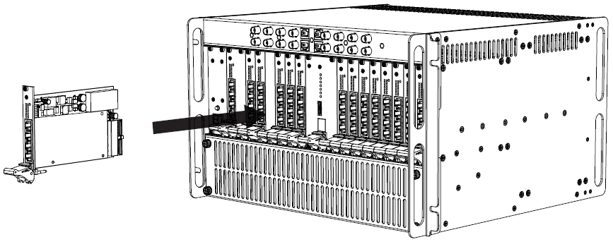
- Gently slide the new board into the slot until the locking tab clicks into place and connector slides snugly into the connector on the midplane.
- Reconnect power
The following image illustrates how to insert hardware components into the OP7000 chassis.
The system must be powered down before changing boards. Failure to do so may damage the equipment.
Changing Mezzanines
The OP7220 is the carrier board on which the mezzanine conditioning boards are installed. Installation is simple and once the conditioning board is firmly pressed into place, the carrier board is ready to be installed in the OP7000.
Two polarized connectors fasten the module and four screws affix it for a more secure connection to the carrier. Make sure that the connectors are properly aligned; they should fit together easily. Use light pressure to push the mezzanine board into the carrier board.
Front and rear board connections
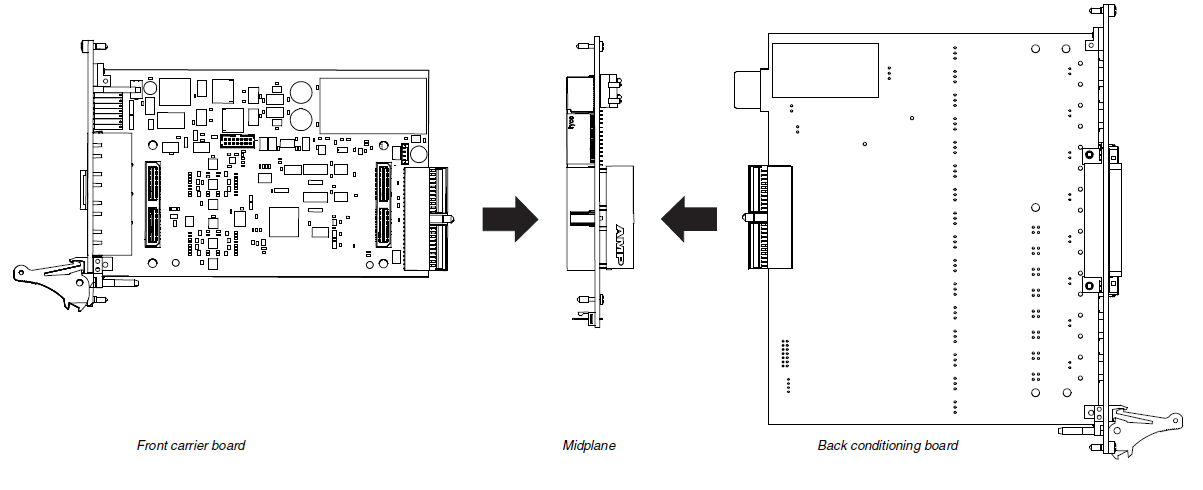
Special attention must be paid to the types of boards that are installed in each of the slots at the front and the rear of the unit. If an analog board is installed in slot 1 at the front of the unit, then an analog conditioning board MUST be installed in slot 1 at the rear of the unit.
Each slot has a track that guides the board into the exact alignment for the connector
OPAL-RT TECHNOLOGIES, Inc. | 1751, rue Richardson, bureau 1060 | Montréal, Québec Canada H3K 1G6 | opal-rt.com | +1 514-935-2323
Follow OPAL-RT: LinkedIn | Facebook | YouTube | X/Twitter


