Documentation Home Page ◇ Hardware Home Page
Pour la documentation en FRANÇAIS, utilisez l'outil de traduction de votre navigateur Chrome, Edge ou Safari. Voir un exemple.
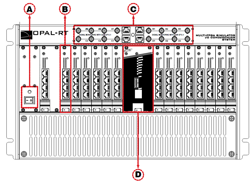
OP7000 Front Interface
A: Power switch with LED
B: Carrier board (OP7220) interfaces:
- 16 red LEDs (8 pairs). Light intensity is directly commensurate to voltage (the higher the voltage, the brighter the LED intensity)1.
- One Status LED with variable color (see table for display description)
| LED | Description |
|---|---|
| Red | Insufficient power voltage for digital board |
| Blinking red | Insufficient power voltage for analog board |
| Blinking orange | No mezzanine upload |
| Orange | Sanity signal absent |
| Yellow | All statuses normal |
| Blinking yellow | Error in analog board even slot |
- One column of 4 RJ45 connectors provide connections to monitor output from mezzanine I/O Each connector represents 4 channels (see OP7000 Installation and Configuration for more detailed information).
C: Monitoring connectors: See OP7000 Installation and Configuration for instructions on using these connectors.
D: OP7161 Front interface providing, from top to bottom :
- Seven LED indicators :
Position | LED | Description |
|---|---|---|
1 | Power | On (green) indicates that the unit is powered up. |
2 | Config | Green indicates that a user-defined configuration (bitstream) is running. Yellow indicates that the safe, default configuration (bitstream) is running. Flashing indicates the configuration is paused. Off indicates that there is no configuration available.. |
3 | Comm | On (green) indicates communication with the PC is in progress. |
4 | Model | On indicates model in use. |
5 | Sync | Green indicates Master synchronization in progress Yellow indicates Slave synchronization in progress |
6 | Fault | Red indicates a fault. |
7 | User-defined | Green/Yellow |
- One JTAG connector for programming functions. Reserved for OPAL-RT technicians’ use
- One RJ45 connector. This connector is DISABLED.
OPAL-RT TECHNOLOGIES, Inc. | 1751, rue Richardson, bureau 1060 | Montréal, Québec Canada H3K 1G6 | opal-rt.com | +1 514-935-2323
Follow OPAL-RT: LinkedIn | Facebook | YouTube | X/Twitter
