Documentation Home Page ◇ Specialized Solutions Home Page
Pour la documentation en FRANÇAIS, utilisez l'outil de traduction de votre navigateur Chrome, Edge ou Safari. Voir un exemple.
OP1210 MMC User Interface
Front Interface
- Power switch. When powered up, the green LED is on
- Status LEDs:
LED Label | Description |
|---|---|
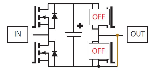
STATUS | On converter is running (transmitting pulses to transistors) Off: converter blocked (sub-module in high impedance (Hi-Z)) |
FAULT | On: fault detected by internal controller Off: normal operation |
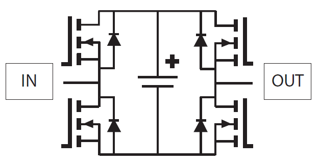
FB CONFIG | On: sub-module in full-bridge operating mode (FB) Off: sub-module in half-bridge operating mode (HB) |
Note: when the converter is in half-bridge mode, all LEDs should be off when the converter is operating.
Rear Interface
OP1210 Standard Configuration
- Fiber optic TX/RX connectors for communication with OP4510.
- Power Cells screw terminal connectors
The first two connect the + and - for the power cells 400V peak, 15Arms, 1.8Kva
The last two connect the + and - for the Auxiliary supply, 48 Vdc, 1A, 48W
OP1210 Submodule Options
.
OPAL-RT TECHNOLOGIES, Inc. | 1751, rue Richardson, bureau 1060 | Montréal, Québec Canada H3K 1G6 | opal-rt.com | +1 514-935-2323
Follow OPAL-RT: LinkedIn | Facebook | YouTube | X/Twitter


