Documentation Home Page ◇ Specialized Solutions Home Page
Pour la documentation en FRANÇAIS, utilisez l'outil de traduction de votre navigateur Chrome, Edge ou Safari. Voir un exemple.
OP1260 User Interface
- Sylvain Ménard
Front Interface

- Start/Stop switch*: Start closes the DC contactor and allows user to connect the DC grid to the converter. Stop opens the contactor and disconnects DC grid*.
- DC Voltage Output LED: when this light is on, it indicates that a DC voltage is present/active on the converter side of the DC contactor.
- Start/Stop switch*: pressing start closes the AC contactor and allows user to connect the AC grid to the converter. Pressing stop opens the contactor and disconnects AC grid.
- L1 L2 L3 LEDs: when this light is on, it indicates that a voltage is present/active on the converter side of the AC controller.
- Emergency Stop*: shuts all contactors and cuts both AC and DC lines to the MMC.
Note: when restarting, make sure that switches and breakers (rear interface) are not tripped. If tripped, they need to be reset (make sure to test fuses in the event of a reset and replace as needed).
* These switches are only operational when permission is given by the model running in the OP4510.
If no permission is given, the switches perform no action.
Rear Interface
OP1260 Standard Configuration
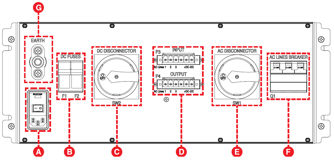
- Power Switch. Power input from rack power bar that will provide auxiliary power to OP1260.
- DC FUSES: overcurrent protection shuts down DC current in the event of an overage.
- DC DISCONNECTOR: provides safety voltage shutdown/isolation on DC lines, with a safety lockout feature for padlocking the disconnector during service.
- P3 INPUT, P4 OUTPUT: P3 connects to the AC and DC power input cables and P4 connects the protection box’s outputs to the OP1261 Measurement Box
- AC DISCONNECTOR: provides safety voltage shutdown/isolation on AC lines, with a safety lockout feature for padlocking the disconnector during service.
- AC LINES BREAKER: overcurrent protection shuts down AC current in the event of an overage. EARTH: (ground) connector
CAUTION: Even if breakers are triggered or fuses are blown, there is still voltage present on the lines. Always use disconnectors to shut off power completely.
DANGER HIGH VOLTAGE: High voltage wiring operations should always be carried out by qualified personnel.
WARNING: Lockout switches before working on equipment.
Wiring Diagram
This is the basic cabling diagram to connect the AC and DC power cables to your OP1260.

DANGER HIGH VOLTAGE: High voltage wiring operations should always be carried out by qualified personnel.
OPAL-RT TECHNOLOGIES, Inc. | 1751, rue Richardson, bureau 1060 | Montréal, Québec Canada H3K 1G6 | opal-rt.com | +1 514-935-2323
Follow OPAL-RT: LinkedIn | Facebook | YouTube | X/Twitter