Documentation Home Page ◇ HYPERSIM Home Page
Pour la documentation en FRANÇAIS, utilisez l'outil de traduction de votre navigateur Chrome, Edge ou Safari. Voir un exemple.
67 - Directional Relay Based on Impedance
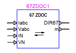
The 67 directional relay can detect the direction of the input current using impedance and torque which are calculated for their respective elements. The relay consists the following elements for detecting the current direction: Positive sequence voltage polarized phase directional (DIRP), negative sequence voltage polarized directional element (DIRQ) and for detecting ground current direction (DIRQG), zero sequence voltage polarized ground current directional element (DIRV), zero sequence current polarized neutral current directional element (DIRI), and zero sequence voltage polarized neutral current directional element (DIRN). The last 4 elements are used to detect the direction for ground currents. This relay can be used in conjunction with overcurrent relays (5051, or 50, 51) to either block a trip signal or permit it from them depending on the application. So, the output of this relay is only the current direction for the aforementioned elements.
That main source for designing this relay was the manual for SEL relays, specifically: SEL-351R [2], SEL-351-5-6-7 [3], SEL-751 [4].
Description
This section describes the different elements in the model: DIRP, DIRQ, DIRV, DIRN, DIRI.
Positive-sequence voltage polarized phase directional element (DIRP)
The phase directional element (DIRP) uses the positive sequence impedance () based on the ratio of (
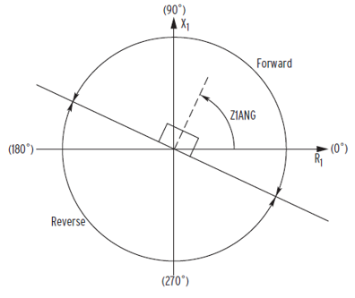
) to determine the location of the fault. It is used for three phase faults. If the positive sequence impedance falls between plus or minus 90 degrees of Z1ANG, which is the characteristic angle of the line, then the relay declares the direction as forward. The line-to-line currents must exceed a pickup current (50P32P) set by the user to enable this element. The unit for 50P32P is amperes and it has a range determined by the secondary transformer side current. The positive sequence voltage must be higher than 0.5 threshold value. If it drops, the value from 3 cycles ago will be used.
It should be noted that phase directional is disabled if there is a strong negative-sequence current and so that element (DIRQ) is enabled. The negative-sequence directional element has priority over phase directional [2].
The outputs of the directional element itself are: FDIRP and RDIRP which show forward and reverse phase current respectively.
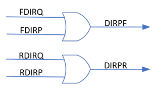
The FDIRP and RDIRP are routed and compared with directions from the negative-sequence element (FDIRQ and RDIRQ). If either of them is 1, the direction for phase is detected as forward (DIRPF), or reverse (DIRPR). This will be explained more in the following sections.
- Equation for calculating the positive sequence impedance:
- Conditions for declaring the fault as forward:
- Pickup current condition:
- Forward and reverse areas in X-R plane based on Z1ANG are shown in the figure below:
Negative-sequence voltage polarized ground and phase current directional element (DIRQ, DIRQG)
The negative-sequence element calculates Z2 from negative sequence current and voltage to determine the fault. It is used for sensing unbalance faults.
This element controls the negative-sequence overcurrent elements. Along with positive-sequence voltage polarized directional elements, it controls the phase overcurrent directional element (DIRQ). Along with zero-sequence ground or neutral currents, it controls the ground or neutral directional elements (DIRQG). The negative-sequence element has priority over phase directional element and if it is enabled, it will disable the phase directional element.
Based on the settings and conditions, the direction of the current might be detected as forward (F) or reverse (R). That is true for both negative sequence directional element for phase direction and for ground direction. So the directions detected by the element are: FDIRQ, RDIRQ, FDIRQG, RDIRQG
Here are the features and characteristics of this element:
- To use the negative-sequence element for ground directional detection, the ground directional option has to be set to DIRQG.
- To enable the negative sequence element, first the negative sequence current, I2 must be higher than the pickup current for forward and reverse direction: 50QFP, 50QRP.
It should be noted the enabling of negative sequence element is for both phase directional and ground directional.
- As an extra security measure, two restraints are applied to the negative-sequence current: positive sequence restraint (a2) and zero-sequence restraint (k2). The following conditions have to be met so the element is enabled.
- The negative sequence impedance, Z2 is calculated from
which is shifted by Z1ANG. Z1ANG is the characteristic angle of the line.
The * sign means it is the conjugate of the complex value.
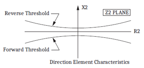
- Z2 must be lower than the forward threshold calculated from the parameter Z2F to detect the current direction as forward. Z2 must be higher than the reverse threshold calculated from the parameter Z2R to detect the current direction as reverse. Z2F and Z2R are set by the user can based on them, the forward and reverse threshold are calculated as the following equations:
Forward threshold Z2
Forward direction FDIRQ, FDIRQG
Z2 Reverse threshold
Reverse direction RDIRQ, RDIRQG
If Forward threshold
If Forward threshold
If Reverse threshold
If Forward threshold
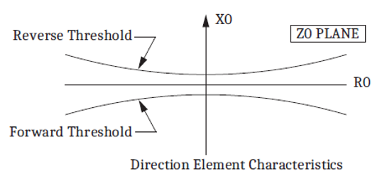
- The operating areas based on Z2 and the thresholds are shown in the figure below:
- The directions FDIRQG and RDIRQG are routed along with other elements to determine the direction of the ground directional element (DIRGF or DIRGR) and neutral ground directional element (DIRN).
Zero-sequence voltage polarized ground current directional element (DIRV)
This element calculates from zero sequence voltage and residual ground current (
) along with shifting them by Z0ANG. Like DIRQG, it is used for unbalance and ground faults.
is the residual current from three phase currents:
By choosing ground directional element to DIRV, if certain conditions are met, the element is enabled and fault current direction is detected as being forward (FDIRV) or reverse (RDIRV). These values are routed along with directions from other elements (DIRI, DIRQG) to determine the direction for the ground directional element (DIRG).
Here are the conditions and calculations that are made in this element:
- Ground directional element is set to DIRV.
- The residual ground current has to be higher than ground directional pickup current for forward direction and reverse direction (50GFP, 50GRP) which are settings made by the user:
- As an extra measure of security, a positive sequence restraint is applied to the zero-sequence current. This factor is a0 and the condition is the following:
- Z0 is calculated from zero sequence voltage and ground current shifted by Z0ANG. Z0ANG is the zero-sequence impedance characteristic angle and is set by the user.
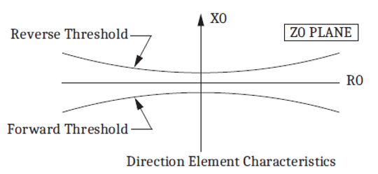
- Z0 has to be lower than the forward threshold calculated from the setting Z0F so the direction is forward. Z0 has to be higher than the reverse threshold calculated from the setting Z0R so the direction is reverse. Z0F and Z0R are zero sequence threshold settings that are changed by the user.
Forward threshold Z0
Forward direction FDIRV
Z0 Reverse threshold
Reverse direction RDIRV
If Forward threshold
If Forward threshold
If Reverse threshold
If Forward threshold
- The operating areas of Z0 based on the thresholds are shown in the figure below:
- The directions FDIRV, RDIRV are routed along with directions from other elements to detect for ground overcurrent directional element (DIRGF or DIRGR) and neutral ground overcurrent directional element (DIRN).
Zero-sequence current polarized neutral current directional element (DIRI)
Unlike other elements which calculate the impedance to detect the direction, this element calculates torque from neutral current (IN) and residual ground current (IG). The angle between them is shifted by INMTA which is set by the user.
The condition for enabling this element is similar to zero sequence voltage polarized ground directional (DIRV) but with a few extra security measures. The nominal neutral current and nominal current which can be chosen by the user to be 1 or 5 A, are used to calculate the threshold.
The direction from this element can be detected as forward (FDIRI), or reverse (RDIRI). They are routed along with other elements to determine the direction for ground directional (DIRG).
Here are the conditions and calculations related to this element:
- Ground directional is set to DIRN.
- Just like for DIRV, the ground current has to be higher than 50GFP and 50GRP pickup currents and there is a positive restraint on I0. These are the conditions to also enable the current polarized element.
- A Neutral Restraint factor (KGN) is applied on the ground current. The following condition is an extra security measure to enable the current opalized directional element.
- The channel IN current from the input to the relay is the neutral current directly from a CT. To enable this element, IN must to be higher than a neutral current threshold which is calculated from the nominal IN current which is set by the user.
IN Nominal can be set to 1 or 5 A.
- The torque which is used to detect the fault direction is calculated from IG and IN shifted by INMTA. INMTA is the maximum torque angle and is set by the user.
- If T is higher than the forward threshold, the direction is forward. If T is negative and lower than the reverse threshold, the direction is reverse. The thresholds are calculated from the nominal phase current and nominal neutral current.
T Forward threshold
Forward direction FDIRI
Reverse threshold T
Reverse direction RDIRI
Forward threshold (Channel IN nominal current)
(Phase nominal current)
Reverse threshold -1 * (Channel IN nominal current)
(Phase nominal current)
- FDIRI and RDIRI are routed along with directions from other elements to detect the direction for ground overcurrent directional element (DIRGF or DIRGR) and neutral ground overcurrent directional element (DIRN)
Zero-sequence voltage neutral current directional element (DIRN)
This element is very similar to DIRV as it also calculates Z0 to determine the direction. The difference is it calculates Z0 from the channel neutral current IN and zero-sequence voltage. This element is also used to detect ground faults.
Here are the conditions and calculations related to this element:
- Ground directional element is set to DIRN.
- The neutral current or channel IN current (IN) must be higher than ground directional pickup current for forward direction and reverse direction (50GFP, 50GRP) divided by 10. This is because this element is more sensitive than those for detecting ground current directions. 50GFP and 50GRP are set by the user.
- Z0 is calculated from zero sequence voltage (V0) and neutral current (IN) shifted by Z0ANG. Z0ANG is the zero-sequence impedance characteristic angle which is set by the user.
- If Z0 is lower than the forward threshold, calculated from Z0F, the direction is forward (FDIRN). If Z0 is higher than the reverse threshold which is calculated from Z0R, the direction is reverse (RDIRN). Z0F and Z0R are settings for Z0 threshold which can be changed by the user.
Forward threshold Z0
Forward direction FDIRN
Z0 Reverse threshold
Reverse direction RDIRN
If Forward threshold
If Forward threshold
If Reverse threshold
If Forward threshold
- The operating areas of Z0 based on the thresholds are shown in the figure below:
- FDIRN, RDIRN are routed along with direction from other elements to detect the direction of neutral overcurrent element (DIRNF or DIRNR).
Direction routing and relay output
The output of the relay is the direction for the following 4 elements:
- Positive sequence phase current direction in forward and reverse: DIRPF, DIRPR.
As shown in below figure, these directions are based on the forward and reverse directions for the phase and negative sequence elements.
- Negative sequence direction in forward and reverse: DIRQF, DIRQR
These directions are the same as the directions from the negative sequence current element itself.
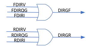
- Ground current direction in forward and reverse: DIRGF, DIRGR
These show the direction of the ground current and are the result of the following logic between directions from DIRV, DIRQG, DIRI.
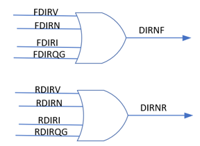
- Neutral current direction in forward and reverse: DIRNF, DIRNR
These show the direction of the neutral fault current and are the result of the following logic between directions from DIRV, DIRI, DIRN, and DIRQG.
Mask and parameters
General Parameters
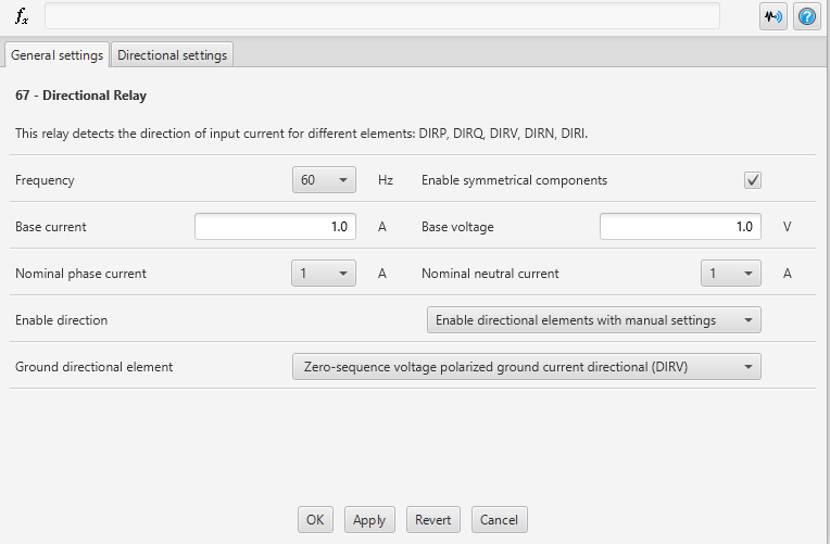
Parameter description under General Settings
| Name | Description | Unit | |
|---|---|---|---|
Current base | Base current, it is used to calculate the secondary current. If the input is already nominal secondary value (1A or 5A), base current can be 1. | A | |
Voltage base | Base voltage | V | |
Enable directional | Enable the use of directional elements along with choice to allow automatic settings for some factors | - | |
Disable directional elements (0) | Disable | ||
Enable directional elements with manual settings (1) | Enable with manual settings | ||
Enable directional elements with automatic settings (2) | Enable with auto settings | ||
Ground directional elements | Option to use one element for ground direction detection. | - | |
Negative-sequence voltage polarized ground current directional (DIRQG) (1) | DIRQG | ||
Zero-sequence voltage polarized ground current directional (DIRV) (2) | DIRV | ||
Zero-sequence current polarized neutral current directional (DIRI) | DIRI | ||
Zero-sequence voltage polarized neutral current directional (DIRN) | DIRN | ||
Nominal Phase Current | Nominal phase current which can be chosen between 1 and 5 A. | A | |
1 (1) | 1 A nominal current | ||
5 (5) | 5 A nominal current | ||
Nominal neutral current | Nominal neutral current which can be chosen between 1 and 5 A. | A | |
1 (1) | 1 A nominal neutral current | ||
5 (5) | 5 A nominal neutral current | ||
Directional Settings
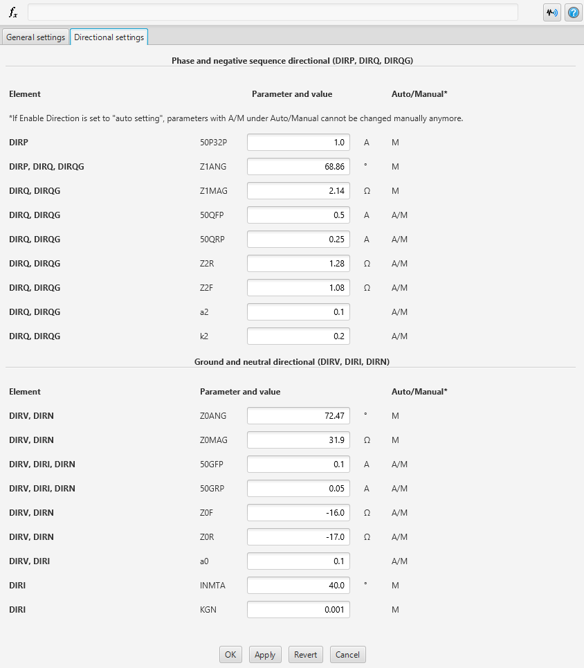
Parameter description under Directional Settings
| Name | Description | DIR | Unit |
|---|---|---|---|
50P32P | Three phase current pickup for phase directional. | DIRP | A, sec |
Z1ANG | Positive-sequence impedance angle. | DIRP DIRQ DIRQG | deg |
Z1MAG | Positive-sequence impedance magnitude. | DIRQ DIRQG | Ohm, sec |
50QRP | Reverse direction negative-sequence current pickup. Has a preset value when “”Enable direction” is chosen to Auto. | DIRQ DIRQG | A, sec |
50QFP | Forward direction negative sequence current pickup. Has a preset value when “”Enable direction” is chosen to Auto. | DIRQ DIRQG | A, sec |
Z2F | Forward direction threshold for Z2. Has a preset value when “”Enable direction” is chosen to Auto. | DIRQ DIRQG | Ohm, sec |
Z2R | Reverse direction threshold for Z2. Has a preset value when “”Enable direction” is chosen to Auto. | DIRQ DIRQG | Ohm, sec |
a2 | Positive-sequence restraint factor, I2/I1. Has a preset value when “”Enable direction” is chosen to Auto. | DIRQ DIRQG | - |
k2 | Zero-sequence restraint factor, I2/I0. Has a preset value when “”Enable direction” is chosen to Auto. | DIRQ DIRQG | - |
Z0ANG | Zero-sequence impedance angle. | DIRV DIRN | deg |
Z0MAG | Zero-sequence impedance magnitude. | DIRV DIRN | Ohm, sec |
50GFP | Forward directional ground current pickup In the DIRN logic, the value for 50GFP is divided by 10. Has a preset value when “”Enable direction” is chosen to Auto. | DIRV DIRN | A, sec |
50GRP | Reverse directional ground current pickup In the DIRN logic, the value for 50GFP is divided by 10. Has a preset value when “”Enable direction” is chosen to Auto. | DIRV DIRN | A, sec |
Z0F | Forward direction threshold for Z0. Has a preset value when “”Enable direction” is chosen to Auto. | DIRV DIRN | Ohm, sec |
Z0R | Reverse direction threshold for Z0. Has a preset value when “”Enable direction” is chosen to Auto. | DIRV DIRN | Ohm, sec |
a0 | Positive sequence restraint factor, I0/I1 Has a preset value when “”Enable direction” is chosen to Auto. | DIRV DIRI | - |
INMTA | Neutral current maximum torque angle. It helps adjust the angle of the neutral current to better define the forward and reverse areas. | DIRI | deg |
KGN | Neutral restraint factor, IG/IN | DIRI | - |
NOTE: When “sec” is mentioned in the Unit column, it means it is from the secondary side of the instrument transformer. So, after going through the ratio.
Inputs, Outputs and Signals Available for Monitoring
Inputs
Name | Description |
Iabc | Three-phase currents |
IN | Current taken from the neutral point of the CT |
Reset | The reset signal for the relay. The relay will be reset when this signal becomes 1 |
Vabc | Three-phase voltages |
VN | Voltage taken from the neutral point of the VT |
Outputs
| Name | Description |
|---|---|
DIR67 | Directions for different fault currents: DIRQF DIRQR DIRPF DIRPR DIRGF DIRGR DIRNF DIRNR |
M | Scopes |
Sensors
| Name | Description | Unit |
|---|---|---|
Iabc(0,1,2) | Three phase currents | A |
Vabc(0,1,2) | Three phase voltages | V |
IN | Neutral current | A |
VN | Neutral voltage | V |
DIR67 | Current direction | - |
FDIRQ | Forward direction for Negative-sequence voltage polarized element | - |
RDIRQ | Reverse direction for Negative-sequence voltage polarized element | - |
FDIRP | Forward direction for positive-sequence voltage polarized phase element | - |
RDIRP | Reverse direction for positive-sequence voltage polarized phase element | - |
FDIRV | Forward direction for zero-sequence voltage polarized ground current element | - |
RDIRV | Reverse direction for zero-sequence voltage polarized ground current element | - |
FDIRQG | Forward direction for negative-sequence voltage polarized ground current element | - |
RDIRQG | Reverse direction for negative-sequence voltage polarized ground current element | - |
FDIRI | Forward direction for zero-sequence current polarized neutral current element | - |
RDIRI | Reverse direction for zero-sequence current polarized neutral current element | - |
FDIRN | Forward direction for zero-sequence voltage polarized neutral current element | - |
RDIRN | Reverse direction for zero-sequence voltage polarized neutral current element | - |
References
[1] Fundamentals and Improvements for Directional Relays, Karl Zimmerman and David Costello, Schweitzer Engineering Laboratories, Inc., October 2010
[2] SEL-351R-4 Recloser Control Instruction Manual, Schweitzer Engineering Laboratories Inc, 2016
[3] SEL-351-5-6-7 Protection System Instruction Manual, Schweitzer Engineering Laboratories Inc, 2020
[4] SEL-751 Feeder Protection Relay Instruction Manual, Schweitzer Engineering Laboratories Inc, 2021
OPAL-RT TECHNOLOGIES, Inc. | 1751, rue Richardson, bureau 1060 | Montréal, Québec Canada H3K 1G6 | opal-rt.com | +1 514-935-2323
Follow OPAL-RT: LinkedIn | Facebook | YouTube | X/Twitter
