Documentation Home Page ◇ Specialized Solutions Home Page
Pour la documentation en FRANÇAIS, utilisez l'outil de traduction de votre navigateur Chrome, Edge ou Safari. Voir un exemple.
BERTA Panels for Islanded Virtual Grid Models
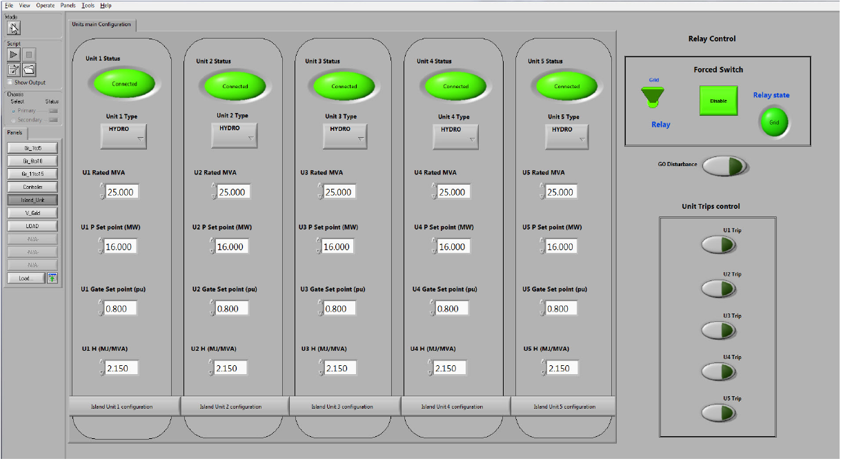
There are two operations panels for the islanded virtual grid:
- The Islanded Grid Main Panel gives access to the modeling parameters of the speed governors and turbines of the five groups that can be operated in parallel with the tested unit;
- The Islanded Grid Configuration Panel gives access to the modeling parameters for the tested units.
The Islanded Virtual Grid Main panel lets you specify the following parameters for each of the five units:
| Unit Status button | Connect or disconnect a unit |
| Unit Type | Select the type for each unit |
| U Rated MVA | Set the rated power in MVA for each unit. |
| U P Set Point (MW) | Set the power set point in MW for each unit. |
| U Gate Set Point | Set the gate set point for the valve position in p.u. |
| U H (MJ/MVA) | Set the inertia in MJ/MVA for each unit. |
| Unit Trips Controls | Enable or disable load shedding when the disturbance Shedding of Selected Units is selected |
| Island Unit Configuration | Configuration of islanded grid unit. Opens a detailed configuration panel showing the models and controllers for the selected unit as shown in the example in Figure 46. |
Note: Since the five units share identical panel options, only unit 1 will be described.
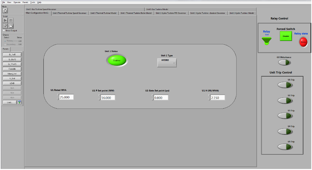
For example, clicking on the Island Unit 1 Configuration button opens the configuration panels for that unit. A series of nine tabs let you change the general configuration and model parameters for each unit and type.
These tabs are the following:
- Main Configuration Unit
- Thermal Turbine Speed Governor
- Thermal Turbine Model
- Thermal Turbine Boiler Model
- Hydraulic Turbine PID Governor
- Hydraulic Turbine Classic Governor
- Hydraulic Turbine Model
- Gas Turbine Speed Governor
- Gas Turbine Model
Islanded Virtual Grid Unit 1 Configuration Tab
Each of the five virtual units included in the BERTA model has the same panel as shown above.
For example, Island Unit 1 panel options are the following:
| Unit Status button | Connect or disconnect a unit |
| Unit Type | Select the type for each unit |
| U Rated MVA | Set the rated power in MVA for each unit. |
| U P Set Point (MW) | Set the power set point in MW for each unit. |
| U Gate Set Point | Set the gate set point for the valve position in p.u. |
| U H (MJ/MVA) | Set the inertia in MJ/MVA for each unit. |
| Unit Trip Controls | Apply a unit trip (line open fault of the unit selected). |
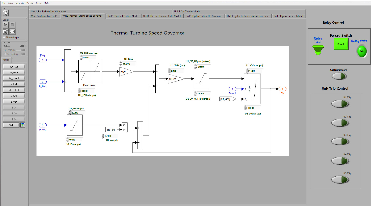
Thermal Turbine Speed Governor Tab
The second tab opens the Thermal Turbine Speed Governor panel which lets you change in real-time the parameters listed.
Turbine Model Tab
This tab displays the panel for a thermal turbine (vapor boiler) model and allows users to change the parameters in real-time. The panel is identical to Figure 43 and the parameters are described in Table 14.
Boiler Model Tab
This tab displays the panel for a vapor boiler thermal turbine model and allows to change its parameters in real-time. The panel is identical to Figure 44 and the parameters are described in Table 15.
Hydraulic Turbine Tab
This tab displays the panel for a Francis hydraulic turbine model and allows to change its parameters in real-time. The panel is identical to Figure 39 and the parameters are described in Table 10.
PID Speed Governor Tab
This tab displays the panel for a Francis turbine PID speed governor model and allows to change its parameters in real-time. The panel is identical to Figure 37 and the parameters are described in Table 8.
Classical Hydro Speed Governor Tab
This tab displays the panel for a Francis turbine classical hydro speed governor model and allows to change its parameters in real-time. The panel is identical to Figure 38 and the parameters are described in Table 9.
Gas Turbine Speed Governor Tab
This tab displays the panel for a gas turbine speed governor model and allows to change its parameters in real-time. The panel is identical to Figure 40 and the parameters are described in Table 11.
Gas Turbine Tab
This tab displays the panel for a gas turbine model and allows to change its parameters in real-time.
The panel is identical to Figure 41 and the parameters are described in Table 12.
OPAL-RT TECHNOLOGIES, Inc. | 1751, rue Richardson, bureau 1060 | Montréal, Québec Canada H3K 1G6 | opal-rt.com | +1 514-935-2323
Follow OPAL-RT: LinkedIn | Facebook | YouTube | X/Twitter


