Documentation Home Page ◇ Specialized Solutions Home Page
Pour la documentation en FRANÇAIS, utilisez l'outil de traduction de votre navigateur Chrome, Edge ou Safari. Voir un exemple.
BERTA On-Site Tests
- BERTA Controller Panel
- BERTA Interface Panel
- BERTA Virtual Grid
- BERTA Panels for Virtual Grid Models
- BERTA Panels for Islanded Virtual Grid Models
- BERTA Load Panel
- BERTA Model Validation Panels
- BERTA Signal Acquisition
On this page:
This chapter describes the procedure to follow when using the BERTA On-Site Tests application.
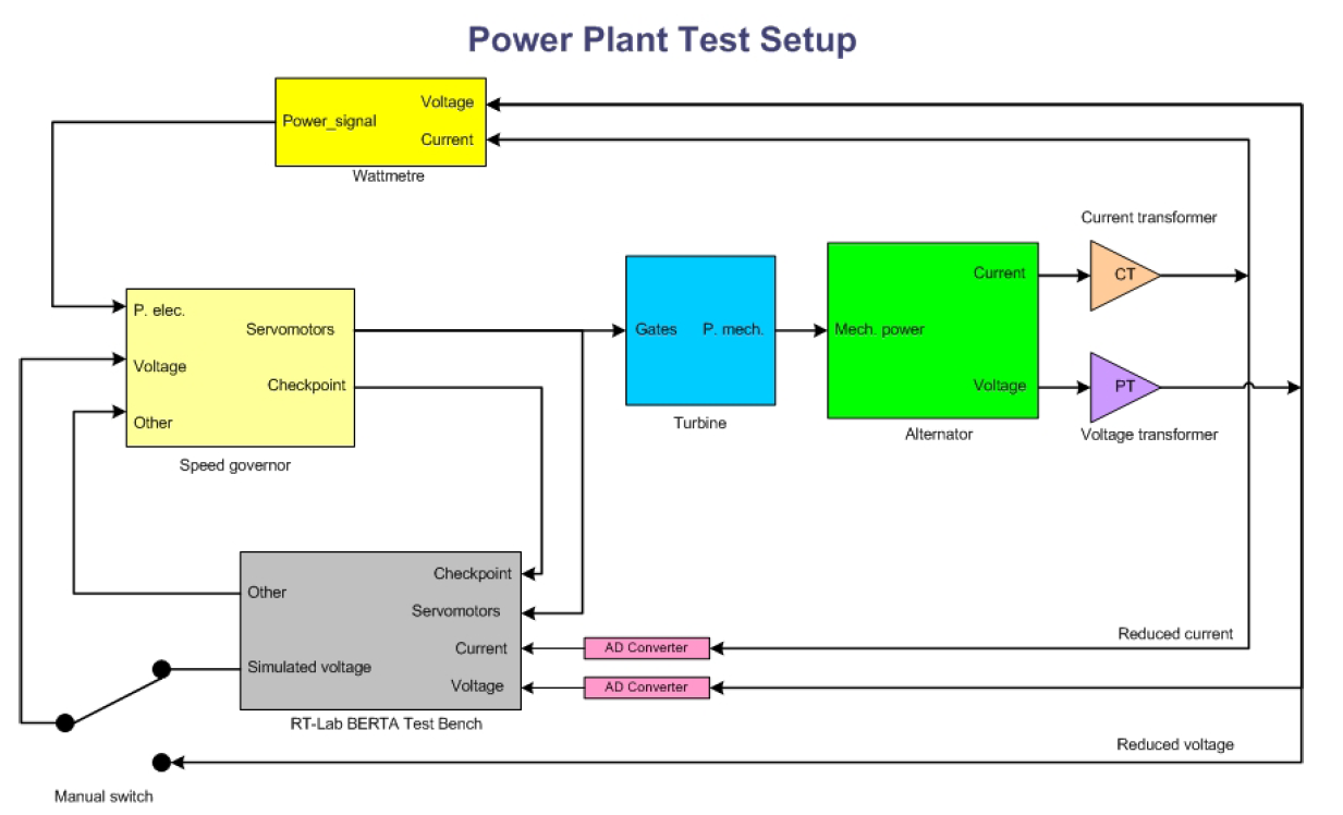
The RT-LAB BERTA test bench carries out tests on power plant speed governors using simulation functions, such as the islanded grid operating mode. AC generator current and voltage signals from the current and voltage transformer secondary windings are converted into low voltage signals.
These signals are sent to the appropriate analog/digital converters of the BERTA test bench.
These alternating low voltage signals are calibrated beforehand so as not to exceed the saturation thresholds of the converters.
An option allows using the test bench in full simulator mode with the speed governor and AC generator models of a virtual grid.
Start-Up
- For on-site tests, make all the necessary connections described in the recommended procedure.
TestDrive Main Screen
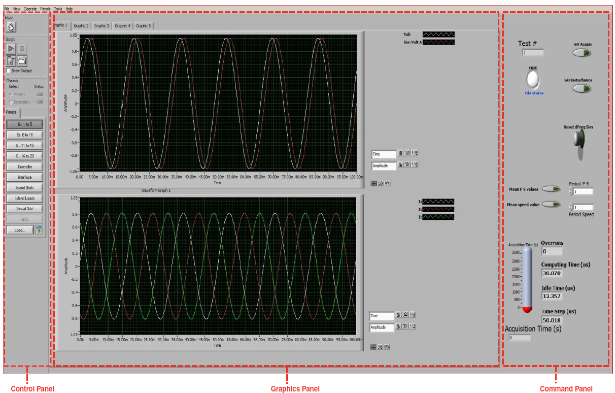
The main screen consists of three sections:
- The Control panel toolbar on the left provides access to a series of panels (Gr. 1 to 5, Gr. 6 to 10, Gr. 11 to 15, Gr. 16 to 21, Controller, Interface, Islanded Units, Islanded Loads, Virtual Grid).
- Refer to the Control Panel Toolbar in the General Introduction for more details.
- The Graphic panel in the middle displays acquisition signals.
- The Command panel toolbar on the right consists of command buttons and fields displaying the progress of the simulation. Refer to the Command Panel Toolbar section for more details.
Control Panel Toolbar
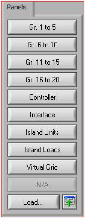
The Panels tab in the Control panel toolbar accesses the following panels:
- Gr. 1 to 5
- Gr. 6 to 10
- Gr. 11 to 15
- Gr. 16 to 20
- Controller
- Interface
- Islanded Units
- Islanded Loads
- Virtual Grid
Command Panel Toolbar for Graphic Panels 1 to 5 and 11 to 21
| Command Panel Toolbar | Toolbar Buttons | Description |
|---|---|---|
GO Acquis | Starts signal acquisition and recording. Click once to start (bright green indicator) and click again to stop (dark green indicator) | |
GO Disturbance | Starts the insert of the disturbance. Click once to start (bright green indicator) and click again to stop (dark green indicator) | |
Reset dFreq Sim | Resets the simulated frequency deviation to zero and resets the initial conditions of the virtual generating units. Switch to the right and hold for 3 seconds | |
Mean PS values | Computes the mean values of power and main servomotor position during the period defined in the Period P S field | |
Period PS | Mean speed value. Computes the mean value of the rotating speed during the period defined in the Period Speed field | |
Period Speed | Mean speed value. Calculates the mean value of the rotation speed during the period defined in the Period Speed field | |
Toolbar Fields | Description | |
The computing time period for the mean values of power and main servomotor position. Refers to command Mean P S values | ||
The computing time period for the mean value of the rotating speed. Refers to command Mean speed value | ||
Test No | Increments the test number by one and the recording file name suffix each time GO Acquis is disabled. There is a 10 seconds delay to allow for the closing of the recording file. | |
File status | Shows the recording file status. (Free or full) | |
Overruns | Increments by one each time the total processing time is longer than the requested time step | |
Computing time | The time required by the workstation to complete one full cycle of all the computations, in μs | |
Idle time | Time margin between each time step and the total computing time, in μs | |
Time Step | Actual time step, in μs | |
Acquisition Time | Displays the acquisition time, as shown in the picture on the left | |
Command Panel Toolbar: Graphic Panels 6 to 10
| Command Panel Toolbar | Toolbar Buttons | Description |
|---|---|---|
Synchronization switch. Click to synchronize the voltage signals generated by BERTA with the grid voltage. Observe the voltage signal curves on graphics 6 | ||
Relay command switch to the speed governor. Toggles the speed governor input signal from the grid frequency to BERTA and vice-versa | ||
Actual (hardware) relay status. Indicates the source of the frequency signal: grid (green) or BERTA (red). A blinking signal signifies that either there is a defect on the relay, either it is not connected | ||
Forcing switch. In an emergency case, forces the relay to toggle immediately, without waiting for the synchronization | ||
For the selection of the tested unit network: the virtual network or the actual network. (Real test in a powerhouse) | ||
GO Acquis | Starts signal acquisition and recording. Click once to start (bright green indicator) and click again to stop (dark green indicator) | |
GO Disturbance | Starts the insert of the disturbance. Click once to start (bright green indicator) and click again to stop (dark green indicator) | |
Reset dFreq Sim. Resets the simulated frequency deviation to zero and resets the initial conditions of the virtual generating units. Switch to the right and hold for 3 seconds | ||
Toolbar Fields | Description | |
Test No. | Increments the test number by one every time GO Acquis is disabled | |
File Status | Shows the file status where the tests are being saved. | |
Acquisition Time | Displays the acquisition time |
Graphic Panels
The Panels tab in the Control panel toolbar provides access to graphic panels each with two monitors (top and bottom). Signal assignments are preset but can be changed. For more details, refer to Creating or Changing Signal Assignments.
GRAPHIC PANELS 1 to 5 | |||
Tab | Monitor Position | Signal Name | Signal Description |
|---|---|---|---|
Graphic 1 | Top | Vab | Generator unit phase to phase voltage A-B (p.u.) |
Sim Volt A | Simulated phase A voltage at desired frequency (p.u.) | ||
Bottom | Ia, Ib, Ic | Phase currents (p.u.) | |
Graphic 2 | Top | Sim dFreq | Simulated frequency deviation (p.u.) |
Bottom | Sim Pelec Total (pu) | Simulated total electric power, including all virtual loads of islanded grid (p.u. on total MVA) | |
Sim Pmec Total (pu) | Simulated total mechanical power, including all virtual generating units of the islanded grid (p.u. on total MVA) | ||
Graphic 3 | Top | Servo1 | Main servomotor stroke (position) (p.u.) |
Mean Servo 1 | Mean servomotor stroke during period P S | ||
Servo 2 | Second servomotor stroke or signalNo. 11 | ||
Bottom | Pelec T U | Measured electric power of the tested unit, including resistive losses of the stator | |
Mean P | Mean mechanical power of the tested unit during period P S | ||
Pmec T U | The mechanical power of the tested unit as estimated by BERTA | ||
Graphic 4 | Top | Servo 1 | Main servomotor stroke (position) (p.u.) |
Pmec T U | The mechanical power of the tested unit as estimated by BERTA | ||
Bottom | Free | ||
Graphic 5 | Top | Pelec T U | Measured electric power of the tested unit, including resistive losses of the stator |
P rotor virtual | Resistive power of rotor (product of electrical torque and rotational speed) of virtual grid AC generating unit | ||
Bottom | Pmec T U | The mechanical power of the tested unit as estimated by BERTA | |
Pmec Virtual | The mechanical power of the virtual grid turbine | ||
GRAPHIC PANELS 6 to 10 | |||
|---|---|---|---|
Tab | Monitor Position | Signal Name | Signal Description |
Graphic 6 | Top | Va | AC generator voltage phase A (p.u.) |
Sim Volt A | Simulated voltage phase A at the desired frequency (p.u.) | ||
Bottom | Va | AC generator voltage phase A (p.u.) | |
| Ia | AC generator current phase A (p.u.) | ||
Graphic 7 | Top | Sum I | Sum of currents for the three phases NOTE: This sum must be zero. or near this value. If not, check connections and calibrations. |
| Sum V p-p | Sum of voltages phase to phase (p.u.) NOTE: This sum must be zero. or near this value. If not, check connections and calibrations. | ||
| Bottom | Va rms | Rms voltage of phase A (p.u.) | |
| Ia rms | Rms current of phase A (p.u.) | ||
Graphic 8 | Top | Sim Pelec Total | Total electrical power simulated, including all the virtual loads of the islanded grid (p.u. on total MVA) |
| Sim Pmec Total | Total mechanical power simulated, including all the virtual generating units of the islanded grid (p.u. on total MVA) | ||
| Bottom | Pelec T U | Electrical power estimated by BERTA | |
| Pmec T U | Mechanical power estimated by BERTA | ||
Graphic 9 | Top | Sim Freq | Simulated frequency (p.u.) |
| Estimated speed T U | Estimated speed of tested AC generator (p.u.) | ||
| Bottom | Va Vb Vc | Three phase voltages of tested AC generator (p.u.) | |
Graphic 10 | Top | Free | |
Bottom | Free | ||
| GRAPHIC PANELS 11 to 15 | |||
|---|---|---|---|
Graphic 11 | Top | Va | AC generator voltage phase A (p.u.) |
Vab | AC generator phase to phase voltage A-B (p.u.) | ||
HV 4 | High voltage, signal No. 4 from AD (p.u.) | ||
Bottom | Vb | AC generator voltage phase B (p.u.) | |
Vbc | AC generator phase to phase voltage B-C (p.u.) | ||
HV 5 | High voltage, signal No. 5 from AD (p.u.) | ||
Graphic 12 | Top | Vc | AC generator voltage phase C (p.u.) |
Vca | AC generator phase to phase voltage C-A (p.u.) | ||
HV 6 | High voltage, signal No. 6 from AD (p.u.) | ||
Bottom | Free | ||
Graphic 13 | Top | Va Vb Vc rms | rms voltages from tested AC generator (p.u.) |
Bottom | Ia Ib Ic | rms currents from tested AC generator (p.u.) | |
Pm thermal | |||
Pm gasturbine | |||
Graphic 14 | Top | MW Total Hydro | Total virtual hydraulic production (MW) |
MW Total Thermal | Total virtual thermal production (MW) | ||
MW Total Gas | Total virtual gas turbine production (MW) | ||
Bottom | MW Total Pmec | Total mechanical power (MW) | |
MW Total Load | Total load before disturbance (MW) | ||
MW Total Pelec | Total electrical power (Load) (MW) | ||
MW Pmec T U | Mechanical power of tested AC generator (MW) | ||
Graphic 15 | Top | Free | |
Bottom | Free | ||
| GRAPHIC PANELS 16 to 21 | |||
|---|---|---|---|
Graphic 16 | Top | U1 Hydro Pm (MW) | Virtual Hydro Unit 1 Pm MW |
U2 Hydro Pm (MW) | Virtual Hydro Unit 2 Pm MW | ||
U3 Hydro Pm (MW) | Virtual Hydro Unit 3 Pm MW | ||
U4 Hydro Pm (MW) | Virtual Hydro Unit 4 Pm MW | ||
U5 Hydro Pm (MW) | Virtual Hydro Unit 5 Pm MW | ||
Bottom | U1 Hydro Gate | Virtual Hydro Unit 1 gate | |
U2 Hydro Gate | Virtual Hydro Unit 2 Gate | ||
U3 Hydro Gate | Virtual Hydro Unit 3 Gate | ||
U4 Hydro Gate | Virtual Hydro Unit 4 Gate | ||
U5 Hydro Gate | Virtual Hydro Unit 5 Gate | ||
Graphic 17 | Top | U1 Thermal Pm (MW) | Virtual Thermal Unit 1 Pm MW |
U2 Thermal Pm (MW) | Virtual Thermal Unit 2 Pm MW | ||
U3 Thermal Pm (MW) | Virtual Thermal Unit 3 Pm MW | ||
U4 Thermal Pm (MW) | Virtual Thermal Unit 4 Pm MW | ||
U5 Thermal Pm (MW) | Virtual Thermal Unit 5 Pm MW | ||
Bottom | U1 Thermal Gate | Virtual Thermal Unit 1 valve | |
U2 Thermal Gate | Virtual Thermal Unit 2 valve | ||
U3 Thermal Gate | Virtual Thermal Unit 3 valve | ||
U4 Thermal Gate | Virtual Thermal Unit 4 valve | ||
U5 Thermal Gate | Virtual Thermal Unit 5 valve | ||
Graphic 18 | Top | U1 Gas Pm (MW) | Virtual TAG Unit 1 Pm MW |
U2 Gas Pm (MW) | Virtual TAG Unit 2 Pm MW | ||
U3 Gas Pm (MW) | Virtual TAG Unit 3 Pm MW | ||
U4 Gas Pm (MW) | Virtual TAG Unit 4 Pm MW | ||
U5 Gas Pm (MW) | Virtual TAG Unit 5 Pm MW | ||
Bottom | U1 Gas Valve | Virtual TAG Unit 1 Valve | |
U2 Gas Valve | Virtual TAG Unit 2 Valve | ||
U3 Gas Valve | Virtual TAG Unit 3 Valve | ||
U4 Gas Valve | Virtual TAG Unit 4 Valve | ||
U5 Gas Valve | Virtual TAG Unit 5 Valve | ||
Graphic 19 | Top | Load 1 MW | Rated Load 1 MW |
Load 2 MW | Rated Load 2 MW | ||
Load 3 MW | Rated Load 3 MW | ||
Load 4 MW | Rated Load 4 MW | ||
Load 5 MW | Rated Load 5 MW | ||
Bottom | Ch. 1 Shedding MW | Shedded MW, Load 1 | |
Ch. 2 Shedding MW | Shedded MW, Load 2 | ||
Ch. 3 Shedding MW | Shedded MW, Load 3 | ||
Ch. 4 Shedding MW | Shedded MW, Load 4 | ||
Ch. 5 Shedding MW | Shedded MW, Load 5 | ||
Graphic 20 | AD Signal No. | Signals 12 to 21 from ADs (V or mA) | |
Graphic 21 | AD Signal No. | Signals 22 to 32 from ADs (V or mA) | |
OPAL-RT TECHNOLOGIES, Inc. | 1751, rue Richardson, bureau 1060 | Montréal, Québec Canada H3K 1G6 | opal-rt.com | +1 514-935-2323
Follow OPAL-RT: LinkedIn | Facebook | YouTube | X/Twitter


