Documentation Home Page ◇ Hardware Home Page
Pour la documentation en FRANÇAIS, utilisez l'outil de traduction de votre navigateur Chrome, Edge ou Safari. Voir un exemple.
OP7000V2 Connecting Monitoring Devices
The OP7000V2 simulator offers quick, single-ended connections, through RJ45 and BNC connectors, to any monitoring device (i.e. oscilloscope, etc.). These BNC jacks let users monitor four channels individually.
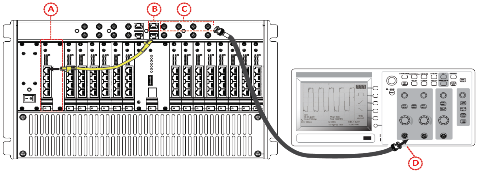
Only connect the RJ45 connectors of the top monitoring section of the chassis with the connectors of the front I/O cards, as shown in the figure below. Connecting these RJ45 connectors to any other cable or device may result in damage to the equipment.
On each front I/O card, the 16 channels are routed to the four RJ45 connectors as indicated on the card: channels 00 to 03 for the top connector, channels 04 to 07 on the second connector, etc.
The monitoring section provides four sections, each section includes one RJ45 connector and 4 BNC connectors. The 16 BNC connectors are labeled A1/A2/A3/A4, B1/B2/B3/B4, C1/C2/C3/C4, D1/D2/D3/D4,
ATTENTION | Buffer amplifiers in the monitoring panel of the chassis have a Gain of 0.1. |
To monitor one channel of a front I/O card:
A Connect one end of the RJ45 cable to the RJ45 connector including the desired I/O channel number, as indicated on the card
For example to monitor channel 00, connect your cable to the top RJ45 connector of the card which is connected to channels 00 to 03 of the card and is labeled 00-03
B Connect the other end of the RJ45 cable to one RJ45 connector of the top section of the chassis. You can use any of the four connectors.
The four channels of the I/O cards are now available on the four BNC jacks next to the RJ45 connector where you connected your cable
C Connect a BNC cable to the BNC jack which corresponds to your channel number.
For example, if you connected your RJ45 cable on the group 00-03 on the I/O card, and connected the cable to the RJ45 next to the B1/B2/B3/B4 BNC jacks, channel 00 is then available on B1, channel 01 on B2, channel 02 and B3 and channel 03 on B4
D Connect the other end of the BNC cable to the monitoring device, like the oscilloscope shown in the figure below.
OPAL-RT TECHNOLOGIES, Inc. | 1751, rue Richardson, bureau 1060 | Montréal, Québec Canada H3K 1G6 | opal-rt.com | +1 514-935-2323
Follow OPAL-RT: LinkedIn | Facebook | YouTube | X/Twitter

